

- CivilFEM Documentation
- CivilFEM Commands Reference
- A commands
- B commands
- ~BLCBDEL
- ~BLCBEND
- ~BLCBLD
- ~BLCBPA
- ~BLCBST
- ~BLF2CMB
- ~BLFDEL
- ~BLFDF
- ~BLFLST
- ~BLPL
- ~BLPLPL
- ~BLSA
- ~BLSB
- ~BLSEND
- ~BLSOLVE
- ~BLSST
- ~BLSTF
- ~BLVA
- ~BLVB
- ~BLVC
- ~BLVD
- ~BLVDEL
- ~BLVEND
- ~BLVGEN
- ~BLVLIB
- ~BLVLST
- ~BLVMDF
- ~BLVR
- ~BLVST
- ~BLWRITE
- ~BMSHDEL
- ~BMSHGEN
- ~BMSHLST
- ~BMSHOFF
- ~BMSHPRO
- ~BRAC
- ~BRADDEL
- ~BRADDPL
- ~BRANG
- ~BRBC
- ~BRCS
- ~BRCSOPT
- ~BRDEF
- ~BRDELEL
- ~BRDELPL
- ~BRGEN
- ~BRHL
- ~BRHLDEL
- ~BRHLMDF
- ~BRINIP
- ~BRIQR
- ~BRMVDL
- ~BRPD
- ~BRPLST
- ~BRSBOX
- ~BRSCN
- ~BRSDEL
- ~BRSDIV
- ~BRSGEN
- ~BRSKTCH
- ~BRSLST
- ~BRSMDF
- ~BRSSLAB
- ~BRSTOCS
- C commands
- ~CALSERC
- ~CBDMS
- ~CFABOUT
- ~CFACTIV
- ~CFCLEAR
- ~CFCONFG
- ~CFEXIT
- ~CFFILE2
- ~CFFL3D
- ~CFGET
- ~CFHBRD
- ~CFHBWR
- ~CFLSSLV
- ~CFLSWRT
- ~CFMP
- ~CFMPDEL
- ~CFMPGEN
- ~CFMPLIB
- ~CFMPLST
- ~CFRAPPN
- ~CFRESUM
- ~CFSAVE
- ~CFSET
- ~CFVGET
- ~CFVLEN
- ~CFVMASK
- ~CHKCON
- ~CHKPRS
- ~CHKSTL
- ~CLPRD
- ~CMB
- ~CMBCLR
- ~CMBDAT
- ~CMBDEF
- ~CMBDEL
- ~CMBINQ
- ~CMBLST
- ~CMBMOD
- ~CMBPRM
- ~CMBSTAT
- ~CODESEL
- ~COMBINE
- ~COST
- ~COSTLST
- ~CPDEF
- ~CPSTDEF
- ~CRLTCOM
- ~CRLTDEF
- ~CRLTDEL
- ~CRLTLST
- ~CRLTUSE
- ~CSDEL
- ~CSECDMS
- ~CSGEN
- ~CSIQR
- ~CSLIB
- ~CSLST
- ~CSMRG
- D commands
- E commands
- F commands
- G commands
- H commands
- I commands
- L commands
- M commands
- P commands
- ~P_SPEC
- ~PCCBDEL
- ~PCCBEND
- ~PCCBPA
- ~PCCBST
- ~PCCTMDF
- ~PCDEL
- ~PCEPDEL
- ~PCEPDEF
- ~PCEPGEN
- ~PCEPMDF
- ~PCLOSS
- ~PCPL
- ~PCPLPL
- ~PCPPDEL
- ~PCPPDEF
- ~PCPPGEN
- ~PCPPMDF
- ~PCTNDEL
- ~PCTNDEF
- ~PCTNGEN
- ~PCTNLST
- ~PCTNMDF
- ~PCTYPE
- ~PL2DINT
- ~PL2DPRS
- ~PLCSBS
- ~PLCSCON
- ~PLCSEC3
- ~PLCSSTR
- ~PLFILE
- ~PLHBMAT
- ~PLHCLPF
- ~PLLSCON
- ~PLLSFOR
- ~PLLSPRS
- ~PLLSSTL
- ~PLLSSTR
- ~PLSEEP
- ~PLSHCLP
- ~PLSHCON
- ~PLSHFOR
- ~PLSHPRS
- ~PLSHSTR
- ~PLTEND
- ~PR2DINT
- ~PR2DPRS
- ~PRCON
- ~PRFOR
- ~PRHCLPF
- ~PRPRS
- ~PRSHCLP
- ~PRSTL
- ~PRSTR
- ~PUSHDEF
- ~PUSHLST
- ~PUSHMOD
- ~PUSHSLV
- R commands
- S commands
- ~SBBMDEF
- ~SBCANNT
- ~SBCLEAR
- ~SBLST
- ~SBPAR
- ~/SBSHOW
- ~SBSMDEF
- ~SBSMMDF
- ~SD2SH
- ~SEC2DIN
- ~SEC2DOU
- ~SECMDF
- ~SEEPAGE
- ~SEEPMOD
- ~SHLDEL
- ~SHLGEN
- ~SHLIPSH
- ~SHLLST
- ~SHLMDF
- ~SHLRNF
- ~SHLSHR
- ~SHLSTL
- ~SLDDEL
- ~SLDLST
- ~SLDMDF
- ~SLDSEC
- ~SLPCIR
- ~SLPCIRK
- ~SLPIN
- ~SLPINK
- ~SLPLST
- ~SLPOPT
- ~SLPPOL
- ~SLPPWP
- ~SLPSOL
- ~SLPTAN
- ~SLPTANK
- ~SSECDMS
- ~SSECLIB
- ~SSECPLT
- ~STSTCFT
- ~STSTDEF
- T commands
- U commands
- V commands
- W commands
- 6.1 CivilFEM Combinations
- 6.2 Results Combination in ANSYS and in CivilFEM
- 6.3 Basic Terminology
- 6.4 Types of Combination Rules
- 6.5 Data Groups
- 6.6 Envelopes
- 6.7 Concomitance at Load and Model Level
- 6.8 Comment about Beam188 and Beam189 Elements
- 6.9 Start State Combinations with Prestressing Tendons
- 6.10 Calculation of All Possible Load Cases
- 6.11 Automatic Load Combinations for Standards
- 11–A.1 Introduction
- 11–A.2 Predesign of Rectangular Sections
- 11–A.3 3D Interaction Diagram
- 11–A.4 Axial Load and Biaxial Bending Checking
- 11–A.5 Axial Load and Biaxial Bending Design (Reinforcement Factor)
- 11–A.6 Axial Load and Biaxial Bending Design (Reinforcement Amount)
- 11–A.7 Calculation Codes
- 11–A.8 Previous Considerations to Shear and Torsion Calculation
- 11–A.9 Shear and Torsion according to Eurocode 2 (ENV 1992–1–1:1991)
- 11–A.10 Shear and Torsion according to Eurocode 2 (EN 1992–1–1:2004/AC:2008) and ITER Design Code
- 11–A.11 Shear and Torsion according to ACI 318–05
- 11–A.12 Shear and Torsion according to ACI 318–14
- 11–A.13 Shear and Torsion according to ACI 318–19
- 11–B.1 Introduction
- 11–B.2 Shear and Torsion according to EHE–98
- 11–B.3 Shear and Torsion according to EHE–08
- 11–B.4 Shear and Torsion according to BS8110
- 11–B.5 Shear and Torsion according to AS3600
- 11–B.6 Shear and Torsion according to GB50010–2002
- 11–B.7 Shear and Torsion according to GB50010–2010
- 11–B.8 Shear and Torsion according to NBR6118
- 11–B.9 Shear and Torsion according to AASHTO Standard Specifications for Highway Bridges
- 11–B.10 Shear and Torsion according to Code of Rules 52–101–03 and SP 63.13330.2012
- 11–B.11 Shear and Torsion according to IS 456
- 11–C.1 Introduction
- 11–C.2 Shear and Torsion according to ACI 349–01 y ACI 349–06
- 11–C.3 Shear and Torsion according to ACI 349–13
- 11–C.4 Cracking Analysis
- 11–C.5 Cracking Checking according Eurocode 2 (ENV 1992–1–1:1991)
- 11–C.6 Cracking Checking according Eurocode 2 (EN 1992–1–1:2004/AC:2008) and ITER Design Code
- 11–C.7 Cracking Checking according to ACI 318–05 and ACI 318–14
- 11–C.8 Cracking Checking according to EHE (EHE–98 and EHE–08)
- 13.1 General Concepts
- 13.2 Design for Bending Moment and Torsion – Wood–Armer Method
- 13.3 Design under Bending Moment and In Plane Loading – CEB–FIP Method
- 13.4 Design according to the Orthogonal Directions Method
- 13.5 Design according to the Most Unfavorable Direction Method
- 13.6 Check and Design for Out–of–Plane Shear Loadings according to Eurocode 2 (ENV 1992–1–1:1991)
- 13.7 Check and Design for Out–of–Plane Shear Loadings according to Eurocode 2 (EN 1992–1–1:2004/AC:2008) and ITER Design Code
- 13.8 Check and Design for Out–of–Plane Shear Loadings according to EHE–98
- 13.9 Check and Design for Out–of–Plane Shear Loadings according to EHE–08
- 13.10 Check and Design for Out–of–Plane Shear Loadings according to Code of Rules 52–101–03 and SP 63.13330.2012
- 13.11 Check and Design for Out–of–Plane Shear Loadings according to ACI 318–05
- 13.12 Check and Design for Out–of–Plane Shear Loadings according to ACI 318–14
- 13.13 Check and Design for Out–of–Plane Shear Loadings according to ACI 318–19
- 13.14 Check and Design for Out–of–Plane Shear Loadings according to ACI 349–01 and ACI 349–06 (Reinforced Concrete)
- 13.15 Check and Design for Out–of–Plane Shear Loadings according to ACI 349–13 (Reinforced Concrete)
- 13.16 Check and Design for In–plane Shear Loadings according to ACI 349–01and ACI 349–06
- 13.17 Check and Design for In–plane Shear Loadings according to ACI 349–13
- 13.18 Check and Design according to ACI 359–04 (Reinforced Concrete)
- 13.19 Check and Design according to ACI 359–04 (Prestressed Concrete)
- 13.20 Cracking Checking according Eurocode 2 (EN 1992–1–1:2004/AC:2008)
- 13.21 Cracking Checking according to ACI 318–05, ACI 318–14 and ACI 318–19
- 13.22 Cracking Checking according to Code of Rules 52–101–03 and SP 63.13330.2012
- 14.1 Introduction
- 14.2 Spectrum Calculation according to Eurocode 8 (ENV–1998–1–1:1994)
- 14.3 Spectrum Calculation according to Eurocode 8 (EN–1998–1:2004)
- 14.4 Spectrum Calculation according to NCSE–94
- 14.5 Spectrum Calculation according to NCSE–02
- 14.6 Spectrum Calculation according to GB50011
- 14.7 Spectrum Calculation according to GB50011–2010
- 14.8 Spectrum Calculation according to IT3274
- 14.9 Spectrum Calculation according to AASHTO LRFD Bridge Design Specifications
- 14.10 Spectrum Calculation according to EAK 2000
- 14.11 Spectrum Calculation according to CALTRANS Seismic Design Criteria
- 14.12 Spectrum Calculation according to the Uniform Building Code (1997)
- 14.13 Spectrum Calculation according to PS 92
- 14.14 Spectrum Calculation according to the Indian Standard 1893
- 14.15 Modal Analysis of the Structure
- 14.16 Modes Combination
- 14.17 Push Over Analysis
- 14.18 Seismic Safety Margin
- 17–A.1 Introduction
- 17–A.2 Definition of Layered Soils
- 17–A.3 Ballast Module
- 17–A.4 Retaining Walls 1 ½ D
- 17–A.5 Slope Stability
- 17–A.6 Mohr–Coulomb Plasticity Model
- 17–A.7 Cam–Clay Plasticity Model
- 17–A.8 Hoek and Brown's Failure Criteria
- 17–A.9 Seepage
- 17–A.10 Earth Pressures
- 17–A.11 Terrain Initial Stress
- /SBSHOW
- ACTMAT
- ACTTIME
- ALTER
- BLCBDEL
- BLCBEND
- BLCBLD
- BLCBPA
- BLCBST
- BLF2CMB
- BLFDEL
- BLFDF
- BLFLST
- BLPL
- BLPLPL
- BLSA
- BLSB
- BLSEND
- BLSOLVE
- BLSST
- BLSTF
- BLVA
- BLVB
- BLVC
- BLVD
- BLVDEL
- BLVEND
- BLVGEN
- BLVLIB
- BLVLST
- BLV;DF
- BLVR
- BLVST
- BLWRITE
- BMSHDEL
- BMSHGEN
- BMSHLST
- BMSHOFF
- BMSHPRO
- BRAC
- BRADDEL
- BRADDPL
- BRANG
- BRBC
- BRCS
- BRCSOPT
- BRDEF
- BRDELEL
- BRDELPL
- BRGEN
- BRHL
- BRHLDEL
- BRHLMDF
- BRINIP
- BRIQR
- BRMVDL
- BRPD
- BRPLST
- BRSCN
- BRSDEL
- BRSDIV
- BRSGEN
- BRSKTCH
- BRSBOX
- BRSLST
- BRSMDF
- BRSSLAB
- BRSTOCS
- CALSERC
- CBDMS
- CFABOUT
- CFACTIV
- CFCLEAR
- CFCONFG
- CFEXIT
- CFFILE2
- CFFL3D
- CFGET
- CFHBRD
- CFHBWR
- CFLSSLV
- CFLSWRT
- CFMP
- CFMPDEL
- CFMPGEN
- CFMPLIB
- CFMPLST
- CFRAPPN
- CFRESUM
- CFSAVE
- CFSET
- CFVGET
- CFVLEN
- CFVMASK
- CHKCON
- CHKPRS
- CHKSTL
- CLPRD
- CMB
- CMBCLR
- CMBDAT
- CMBDEF
- CMBDEL
- CMBINQ
- CMBLST
- CMBMOD
- CMBPRM
- CMBSTAT
- CODESEL
- COMBINE
- COST
- COSTLST
- CPDEF
- CPSTDEF
- CRLTCOM
- CRLTDEF
- CRLTDEL
- CRLTLST
- CRLTUSE
- CSDEL
- CSECDMS
- CSGEN
- CSIQR
- CSLIB
- CSLST
- CSMRG
- DAHEAD
- DASEEP
- DEFSPEC
- DIMCON
- DIMPRS
- DIMPRS
- DIMSTL
- DLHEAD
- DLSEEP
- EFFPRES
- EFSAPPL
- EFSCALC
- EFSLST
- ENVDEF
- ENVDEL
- ENVELOP
- ETHSF
- ETHSFE
- FL3DRES
- FMREAD
- FMWRITE
- FRMBS
- FRMCPY
- FRMCR
- FRMDEF
- FRMDEL
- FRMGEN
- FRMGT
- FRMLDS
- FRMLST
- FRMMDL
- FRMVHS
- FRTRCK
- GENSPEC
- GENTEN
- GRCSBS
- GRCSCON
- GRCSEC3
- GRCSSTR
- GRSLPD
- GRSLPR
- GTPD
- HBSOLVE
- HCLPFCN
- HCLPFST
- IDHCLPF
- ILCLOSE
- ILOPEN
- ISOBAR
- L_MOD
- L_SPEC
- LINCMB
- LINLST
- LPRNSOL
- LPSOLVE
- LSTFMT
- MEMBDEL
- MEMBGEN
- MEMBLST
- MEMBPRO
- MOD_SF
- MODLSOL
- P_SPEC
- PCCBDEL
- PCCBEND
- PCCBPA
- PCCBST
- PCCTMDF
- PCDEL
- PCEPDEF
- PCEPDEL
- PCEPGEN
- PCEPMDF
- PCLOSS
- PCPL
- PCPLPL
- PCPPDEF
- PCPPDEL
- PCPPGEN
- PCPPMDF
- PCTNDEF
- PCTNDEL
- PCTNGEN
- PCTNLST
- PCTNMDF
- PCTYPE
- PL2DINT
- PL2DPRS
- PLCSBS
- PLCSCON
- PLCSEC3
- PLCSSTR
- PLFILE
- PLHBMAT
- PLHCLPF
- PLLSCON
- PLLSFOR
- PLLSPRS
- PLLSSTL
- PLLSSTR
- PLSEEP
- PLSHCLP
- PLSHCON
- PLSHFOR
- PLSHPRS
- PLSHSTR
- PLSHPRS
- PLTEND
- PR2DINT
- PR2DPRS
- PRCON
- PRFOR
- PRHCLPF
- PRPRS
- PRSHCLP
- PRSTL
- PRSTR
- PUSHDEF
- PUSHLST
- PUSHMOD
- PUSHSLV
- RCVWRT
- REDEF
- REDEL
- RETROFT
- RNFDEF
- RNFMDF
- SBBMDEF
- SBCANNT
- SBCLEAR
- SBLST
- SBPAR
- SBSMDEF
- SBSMMDF
- SD2SH
- SEC2DIN
- SEC2DOU
- SECMDF
- SEEPAGE
- SEEPMOD
- SHLDEL
- SHLGEN
- SHLIPSH
- SHLLST
- SHLMDF
- SHLRNF
- SHLSHR
- SHLSTL
- SLDDEL
- SLDLST
- SLDMDF
- SLDSEC
- SLPCIR
- SLPCIRK
- SLPIN
- SLPINK
- SLPLST
- SLPOPT
- SLPPOL
- SLPPWP
- SLPSOL
- SLPTAN
- SLPTANK
- SSECDMS
- SSECLIB
- SSECPLT
- STSTCFT
- STSTDEF
- TENLD
- TERDEF
- TERDEL
- TERGEN
- TERLST
- TETHEX
- TIS
- TN2DIN
- TNADDEL
- TNADDPL
- TNADV
- TNGEN
- TNINIP
- TNSKTCH
- TPLST
- TPHASE
- TPOST
- TPSET
- TREFINE
- TRGDEF
- TRGDEL
- TRGLST
- TRGUPT
- TSOLVE
- TSTEP
- TTRUSS
- UNITS
- UPDATE
- VARTH
- VERIF
- VWHTML
- VWTXT
- VWXLS
- WALLANC
- WALLGEN
- WALLINI
- WALLJNT
- WALLMOD
- WALLSOL
- WALLSTP
- WATTAB
- WEIGHT
- WTSLP
- WTSOLVE
Beam & Shell Properties
The following window creates a beam property (New Beam button, ~BMSHPRO and ~BMSHOFF commands) or shell property (New Shell button, ~BMSHPRO command). In this window, the user may also Modify (~BMSHPRO and ~BMSHOFF commands), Delete (~BMSHDEL command), Copy (~BMSHGEN command) or List (~BMSHLST command) their properties.
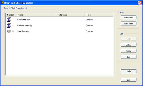
Beam Properties
The following window is displayed when modifying or creating a beam property:
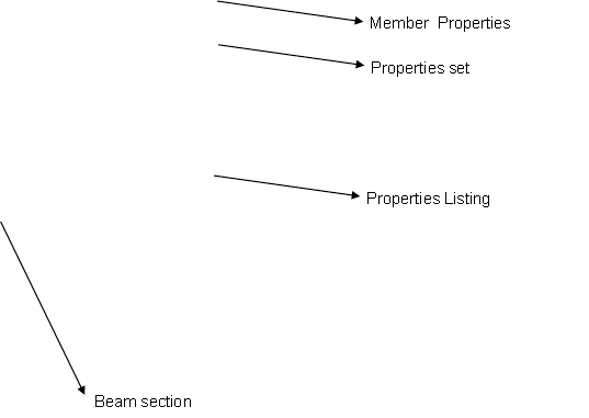
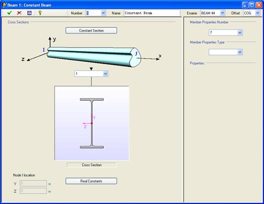
This window is divided in:
· Upper menu – The beam’s general properties are defined here: Number, Name, Beam type (Ename) and Offset location (Offset).
· Cross Section (left side) – where the type of beam section is chosen, and its offsets can be seen and modified.
· Member Properties (right side) – where member properties of the beam are chosen.
In the left side (Cross Section), it is possible to choose if the beam is of constant section or of variable section (pressing on the Constant Section button the screen will change and will display Variable Section)
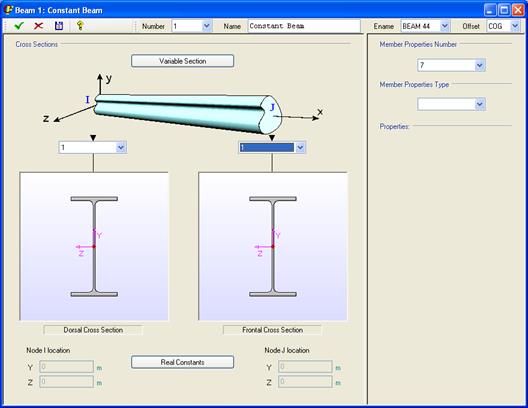
There is a button in the bottom side to display the Real Constants assigned to the beam.
Node location (Beam offsets)
When creating a BEAM44 or BEAM54 element type, the nodes location can be modified by entering an offset (~BMSHOFF command).
There is a combo box in the upper menu which displays the kind of offset de beam will have:
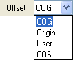
· COG – The node is located at the centre of gravity of the section.
· Origin – The node is located at the section’s axis origin.
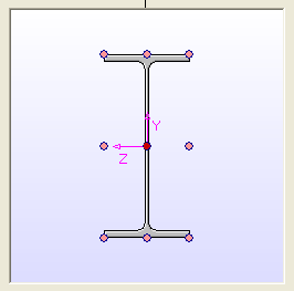
· User – The node is defined by entering its coordinates in the edit boxes located under the cross section picture. These coordinates are referred to the section axis. It is alos possible to select any of the nine typified points on the section, by simply clicking on any of them:
· COS – The node is located at the shear centre of the section.
Shell Properties
The window is the same in the case of Shell Properties, but beam ends (sections) are substituted by shell ends (vertices). Instead of displaying each end, two fields where the vertex Thickness and the Material are shown.
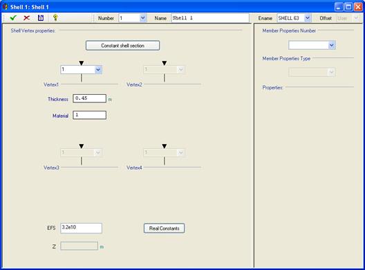
For SHELL63 elements, the Elastic Foundation Stiffness (EFS) edit box is available.
For SHELL181 and 281 elements, an offset can be defined to locate the node at the TOP of the shell element, at the BOTTOM or at any other location defined by the Z coordinate, measured from the shell's mid-plane.
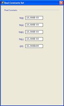
In both windows, Beam Properties and Shell Properties, by pressing the Real Constants button, a dialog is opened in which the Real Constants that will be created in ANSYS are shown.
Related commands: