

PILE CAPS
The aim of this utility is to accurately check pile caps and design the configuration of piles. The three options include:
The created model will have defined components in order to manipulate it easily.
POLYGONAL PILE CAPS
This type of pile wailing has the following characteristics:
· Circular or regular polygonal slab.
· All piles must be circular with the same characteristics.
· The structure will be under the loads transmitted by a circular or rectangular pillar that will be located at the centre of the slab, in addition to its self weight and to a possible surface load extended on the entire slab.
· The terrain can be made up by one or several horizontal layers and each one of them can be cohesionless or cohesive.
· The slab is modeled using SHELL43 elements and the piles by BEAM4 elements.
· The simulation of the friction with the terrain, the point effect and the horizontal ballast module (reaction of the terrain on the piles) is done with LINK8 elements with plasticity to simulate the situation in which the ultimate strength values are reached.
· The reinforcement design can be done in two ways:
o Rigid Pile Caps. In this case the Strut and Tie method is used, explained in the Theory Manual.
o Flexible Pile Caps. In this case the user can choose between the Wood-Armer method and the one of the CEB-FIP Model code.
DATA ENTRY
The window for this pile cap design is made up by a series of sections, shown by the labels at the top of the screen:
The data entry is done in a simplified way, through interactive windows and guided by the program.
The meaning of each parameter or data to enter is explained by moving the cursor over the corresponding text (a tool tip will appear), although it is recommended to read the Theory Manual for a better understanding of what the program is doing.
NOTE: If in the spread list appears a ND> it means that the value is not defined correctly:

Following, the windows CivilFEM will show for the data entry are shown.
GEOMETRY
In the first window, the slab geometry is defined, number of piles, etc.
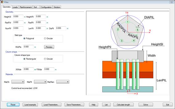
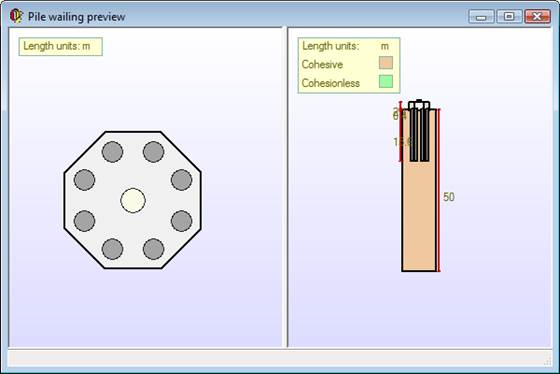
Clicking Preview bottom it will open a preview window like herein below:
LOADS
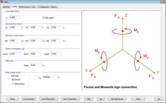
The loads on the slab are defined in the second screen (Forces and moments, surface load, type of loads, etc.).
REINFORCEMENT
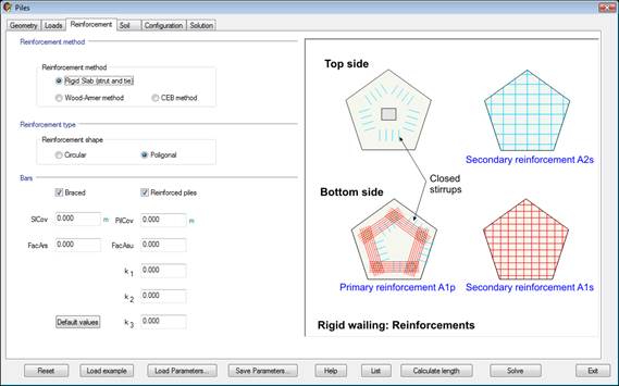
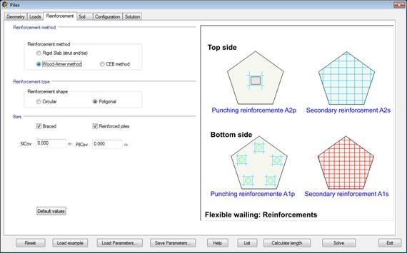
This tab groups the reinforcement type parameters.
The window will change depending on the type of wailing chosen: rigid or flexible.
SOIL
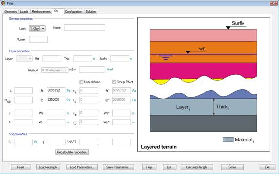
To finish defining the model, it is necessary to select the layered terrain on which the pile cap is defined. A few additional parameters must also be set.
CONFIGURATION
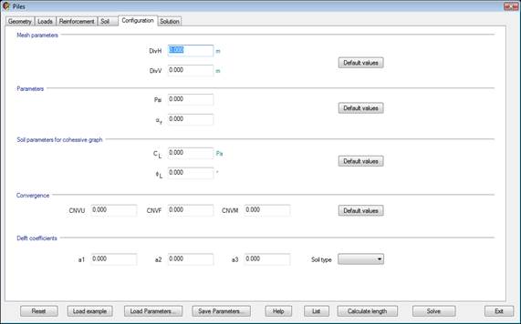
The configuration parameters include Mesh control parameters and convergence and tolerance for the iterations. Default values can be set.
SOLUTION
Under this tab, the design final values are shown.
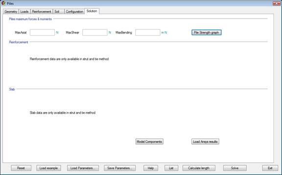
“Load Ansys results” button loads previous obtained results after pressing Solve button.
“Pile Strength graph” button shows the pile strength graph in Ansys. It is necessary to have the results previously loaded with the “Load Ansys results” button.
CALCULATE LENGTH
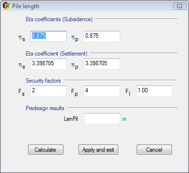
Clicking on the “Calculate length” button in the main dialog opens the CivilFEM window to predesign the pile length necessary for the chosen materials, loads and terrains.
It is possible to calculate this length as many times as needed changing the parameters in the window. Once we get the desired length we click on the “Apply and exit” button.
PARAMETER EXPLANATION
GEOMETRY TAB
|
HeightEn |
Upper pile cap height. |
|
HeightPil |
Head pile height. |
|
RadPol |
Pile cap radius. |
|
RadPil |
Pile situation radius. |
|
NumPil |
Number of pile. |
|
LenPil |
Pile length. |
|
DiaPil |
Pile diameter. |
|
Slab Type |
Polygonal or circular. |
|
WidPla |
Slab width. |
|
Column Shape Type |
Circular or rectangular. |
|
X |
X dimension column (if rectangular). |
|
Y |
Y dimension column (if rectangular). |
|
Diameter |
Column diameter (if circular). |
|
MatSh |
Slab material. |
|
MatPil |
Pile material. |
|
MatRein |
Reinforcement material. |
LOADS TAB
|
GammaF |
Load Factor. |
|
Fx |
X axis force. |
|
Fy |
Y axis force. |
|
Fz |
Z axis force. |
|
Mx |
X axis moment. |
|
My |
Y axis moment. |
|
Mz |
Z axis moment. |
|
AcelX |
X gravity acceleration. |
|
AcelY |
Y gravity acceleration. |
|
AcelZ |
Z gravity acceleration. |
|
Qslab |
Pressure on slab. |
|
|
Geotechnical/Structural pile maximum stress |

REINFORCEMENT TAB
Reinforcement method.
- Rigid pile cap (strut and tie).
- CEB method.
- Wood-Armer method.
Reinforcement shape (Circular or Polygonal).
Bars
- Braced
- Reinforced piles
|
SlCov |
Slab geometrical cover. |
|
PilCov |
Pile geometrical cover. |
|
FacArs |
Secondary reinforcement factor (strut and tie method). |
|
FacAsu |
Secondary upper reinforcement factor (strut and tie method). |
|
k1 |
Concrete compression strength factor (strut and tie method). |
|
k2 |
Steel elastic limit security factor (default value = 0.92). |
|
k3 |
Stirrups analysis factor. |
SOIL TAB
|
General Properties and geometry: |
|
|
Ueth |
Terrain number. |
|
Name |
Terrain name. |
|
Nlayer |
Number of layers. |
|
|
|
|
Layer Properties: |
|
|
Layer |
Selected layer number. |
|
Mat |
Selected layer material. |
|
Thick |
Selected layer thickness. |
|
HeifhtT |
Terrain height. |
|
Method |
Horizontal ballast module method. |
|
HBM |
Horizontal ballast module. |
|
Group effect |
Taking or not into account group effect. |
|
User defined |
Group effect coefficients defined by user. |
|
l |
Cohesion coefficient if l=1 cohesive soil, if >1 cohesionless). |
|
fs |
Unitary skin friction. |
|
fs* |
Unitary skin friction with group effect. |
|
Ncb |
Bearing capacity factor. |
|
hs |
Skin subsidence group effect coefficient |
|
fp |
Unitary point resistance. |
|
fp* |
Unitary point resistance with group effect. |
|
hp |
Point subsidence group effect coefficient. |
|
g |
Shaft deformability factor. |
|
Ws |
Skin displacement. |
|
Ws* |
Skin displacement with group effect. |
|
hs |
Skin settlement group effect coefficient. |
|
d |
Settlement factor. |
|
Wp |
Point displacement. |
|
Wp* |
Point displacement with group effect. |
|
hp |
Point settlement group effect coefficient. |
|
|
|
|
Soil Properties: |
|
|
c |
Cohesion. |
|
f |
Internal friction angle. |
|
NSPT |
Number of blows obtained in the Standard Penetration Test. |
|
|
Unconfined compressive strength. |


CONFIGURATION TAB
|
Mesh Parameters: |
|
|
DivH |
Slab horizontal division’s size. |
|
DivV |
Pile vertical division’s size. |
|
|
|
|
Parameters: |
|
|
Psi |
Et/E springs ratio. |
|
a |
Slab decrease ratio. |
|
|
|
|
Soil Parameters for cohesive graph: |
|
|
|
Cohesion limit for cohesive soils. |
|
|
Internal friction angle limit for cohesive soils. |
|
|
|
|
Convergence: |
|
|
CNVU |
Displacement convergence criterion. |
|
CNVF |
Forces convergence criterion, |
|
CNVM |
Bending moment’s convergence criterion. |
|
|
|
|
Delft Coefficients: |
|
|
a1 |
Delft passive coefficient. |
|
a2 |
Delft active coefficient. |
|
a3 |
Delft safety coefficient. |
|
|
|
|
Soil Type |
Cohesive or cohesionless. |


SOLUTION TAB
|
Piles maximum forces and moments: |
|
|
MaxAxial |
Maximum axial force. |
|
MaxShear |
Maximum shear force. |
|
MaxBending |
Maximum bending force. |
|
|
|
|
Reinforcement: |
|
|
NpiH |
Axial force limit of concrete pile. |
|
NpiS |
Axial force limit of reinforcement pile. |
|
AsPil |
Axial+Bending reinforcing steel in piles. |
|
AsPilS |
Shear reinforcing steel in piles. |
|
AsPl |
Steel in primary reinforcement. |
|
AsSL |
Steel in secondary reinforcement. |
|
AsSu |
Steel in upper reinforcement. |
|
Asu |
Stirrups reinforcement. |
|
StrutA |
Strut compression area. |
|
NS |
Strut compression axial force. |
|
StrutStr |
Strut compression axial force capacity. |
|
WidPla |
Minimum shell thickness needed. |
CALCULATE LENGTH
|
Eta coefficients (Subsidence) |
|
|
hs |
Subsidence Eta skin factor. |
|
hp |
Subsidence Eta point factor. |
|
Eta coefficients (Settlement) |
|
|
hs |
Settlement Eta skin factor. |
|
hp |
Settlement Eta point factor. |
|
Security Factors |
|
|
Fs |
Security skin factor. |
|
Fp |
Security point factor. |
|
Fl |
Load security factor. |
|
Predesign results |
|
|
LenPil |
Pile length calculated. |
RELATED COMMANDS:
RECTANGULAR PILE CAPS
This type of pile cap has the following characteristics:
· Rectangular slab.
· All piles must be circular with the same characteristics.
· The pillar must be rectangular and can be located anywhere of the slab.
· The structure will be under the loads transmitted by the pillar in addition to its self weight and to a possible surface load extended on the entire slab.
· The terrain can be made up by one or several horizontal layers and each one of them can be cohesionless or cohesive.
· The slab is modeled using SHELL43 elements and the piles by BEAM4 elements.
· The simulation of the friction with the terrain, the point effect and the horizontal ballast module (reaction of the terrain on the piles) is done with LINK8 elements with plasticity to simulate the situation in which the ultimate strength values are reached.
· The reinforcement design can be done in two ways:
o Rigid Pile Cap. In this case the Strut and Tie method is used, explained in the Theory Manual.
o Flexible Pile Cap. In this case the user can choose between the Wood-Armer method and the one of the CEB-FIP Model code.
DATA ENTRY
The data entry is done in a simplified way similar to previous option, through interactive windows and guided by the program.
The meaning of each parameter or data to enter is explained by moving the cursor over the corresponding text (a tool tip will appear), although it is recommended to read the Theory Manual for a better understanding of what the program is doing.
NOTE: If in the spread list appears a ND> it means that the value is not defined correctly:
The window for this pile cap design is made up by a series of sections, shown by the labels at the top of the screen:
Following, the windows CivilFEM will display for the data entry are shown.
GEOMETRY
In the first window, the slab geometry is defined, number of piles, etc.
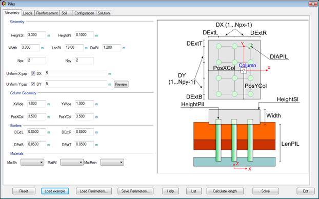
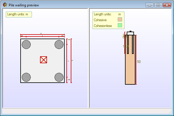
Clicking Preview bottom it will open a preview window like herein below:
LOADS
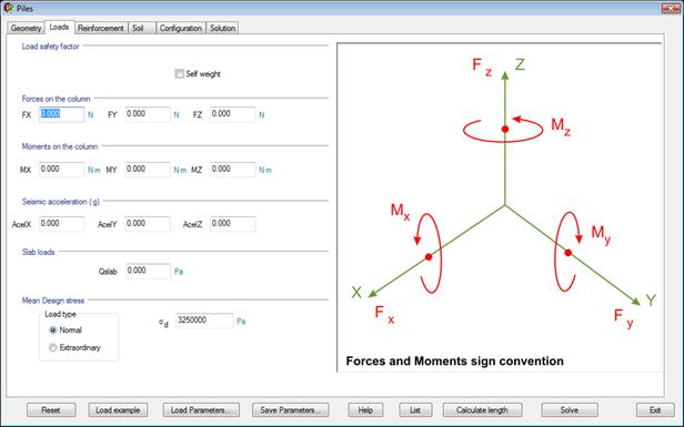
The loads on the slab are defined in the second screen (Forces and moments, surface load, type of loads, etc.).
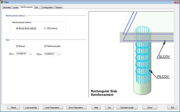
REINFORCEMENT
This tab groups the reinforcement type parameters.
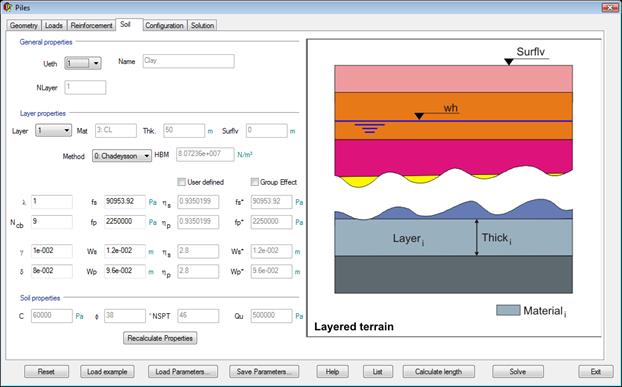
SOIL
To finish defining the model, it is necessary to select the layered terrain on which the pile cap is defined. A few additional parameters must also be set.
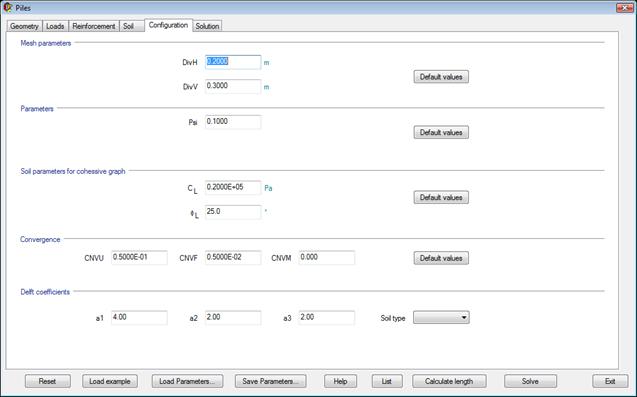
CONFIGURATION
The configuration parameters include Mesh control parameters and convergence and tolerance for the iterations. Default values can be set.
SOLUTION
Under this tab, the design final values are shown.
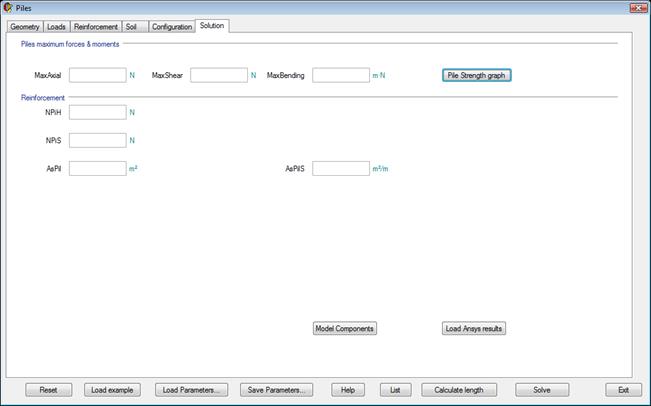
“Load Ansys results” button loads previous obtained results after pressing the “Solve” button.
“Pile Strength graph” button shows the pile strength graph in Ansys. It is necessary to previously load the results through the “Load Ansys results” button.
CALCULATE LENGTH
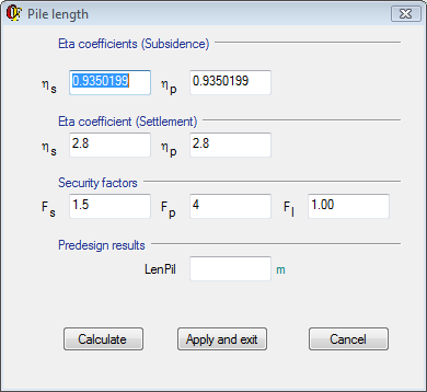
Clicking on the “Calculate length” button in the main dialog opens the CivilFEM window to predesign the pile length necessary for the chosen materials, loads and terrains.
It is possible to calculate this length as many times as needed changing the parameters in the window. Once we get the desired length we click on the Apply and exit button.
PARAMETER EXPLANATION
GEOMETRY TAB
|
HeightEn |
Upper pile cap height. |
|
HeightPil |
Head pile height. |
|
WidPla |
Slab width. |
|
LenPil |
Pile length. |
|
DiaPil |
Pile diameter. |
|
Npx |
Number of piles in X axis. |
|
Npy |
Number of piles in Y axis. |
|
|
|
|
Column geometry |
|
|
XWide |
X wide column |
|
YWide |
Y wide column |
|
Xpos |
X position column |
|
YPos |
Y position column |
|
|
|
|
Borders |
|
|
DextL |
Left slab flange as picture shows. |
|
DextR |
Right slab flange as picture shows. |
|
DextB |
Bottom slab flange as picture shows. |
|
DextT |
Top slab flange as picture shows. |
|
|
|
|
MatSh |
Slab material. |
|
MatPil |
Pile material. |
|
MatRein |
Reinforcement material. |
LOADS TAB
|
GammaF |
Load Factor. |
|
Fx |
X axis force. |
|
Fy |
Y axis force. |
|
Fz |
Z axis force. |
|
Mx |
X axis moment. |
|
My |
Y axis moment. |
|
Mz |
Z axis moment. |
|
AcelX |
X gravity acceleration. |
|
AcelY |
Y gravity acceleration. |
|
AcelZ |
Z gravity acceleration. |
|
Qslab |
Pressure on slab. |
|
|
Geotechnical/Structural pile maximum stress |
REINFORCEMENT TAB
Reinforcement method.
- CEB method.
- Wood-Armer method.
Bars
- Braced.
- Reinforced piles.
|
SlCov |
Slab geometrical cover. |
|
PilCov |
Pile geometrical cover. |
SOIL TAB
|
General Properties and geometry: |
|
|
Ueth |
Terrain number. |
|
Name |
Terrain name. |
|
Nlayer |
Number of layers. |
|
|
|
|
Layer Properties: |
|
|
Layer |
Selected layer number. |
|
Mat |
Selected layer material. |
|
Thick |
Selected layer thickness. |
|
HeifhtT |
Terrain height. |
|
Method |
Horizontal ballast module method. |
|
HBM |
Horizontal ballast module. |
|
Group effect |
Taking or not into account group effect. |
|
l |
Cohesion coefficient if l=1 cohesive soil, if >1 cohesionless). |
|
fs |
Unitary skin friction. |
|
fs* |
Unitary skin friction with group effect. |
|
Ncb |
Bearing capacity factor. |
|
hs |
Skin subsidence group effect coefficient. |
|
fp |
Unitary point resistance. |
|
fp* |
Unitary point resistance with group effect. |
|
hp |
Point subsidence group effect coefficient. |
|
g |
Shaft deformability factor. |
|
Ws |
Skin displacement. |
|
Ws* |
Skin displacement with group effect. |
|
hs |
Skin settlement group effect coefficient. |
|
d |
Settlement factor. |
|
Wp |
Point displacement. |
|
Wp* |
Point displacement with group effect. |
|
hp |
Point settlement group effect coefficient. |
|
|
|
|
Soil Properties: |
|
|
c |
Cohesion. |
|
f |
Internal friction angle. |
|
NSPT |
Number of blows obtained in the Standard Penetration Test. |
|
|
Unconfined compressive strength. |
CONFIGURATION TAB
|
Mesh Parameters: |
|
|
DivH |
Slab horizontal division’s size. |
|
DivV |
Pile vertical division’s size. |
|
|
|
|
Parameters: |
|
|
Psi |
Et/E springs ratio. |
|
a |
Slab decrease ratio. |
|
|
|
|
Soil Parameters for cohesive graph: |
|
|
|
Cohesion limit for cohesive soils. |
|
|
Internal friction angle limit for cohesive soils. |
|
|
|
|
Convergence: |
|
|
CNVU |
Displacement convergence criterion. |
|
CNVF |
Forces convergence criterion, |
|
CNVM |
Bending moment’s convergence criterion. |
|
|
|
|
Delft Coefficients: |
|
|
a1 |
Delft passive coefficient. |
|
a2 |
Delft active coefficient. |
|
a3 |
Delft safety coefficient. |
|
|
|
|
Soil Type |
Cohesive or cohesionless. |
SOLUTION TAB
|
Piles maximum forces and moments: |
|
|
MaxAxial |
Maximum axial force. |
|
MaxShear |
Maximum shear force. |
|
MaxBending |
Maximum bending force. |
|
|
|
|
Reinforcement: |
|
|
NpiH |
Axial force limit of concrete pile. |
|
NpiS |
Axial force limit of reinforcement pile. |
|
AsPil |
Axial+Bending reinforcing steel in piles. |
|
AsPilS |
Shear reinforcing steel in piles. |
CALCULATE LENGTH
|
Eta coefficients (Subsidence) |
|
|
hs |
Subsidence Eta skin factor. |
|
hp |
Subsidence Eta point factor. |
|
Eta coefficients (Settlement) |
|
|
hs |
Settlement Eta skin factor. |
|
hp |
Settlement Eta point factor. |
|
Security Factors |
|
|
Fs |
Security skin factor. |
|
Fp |
Security point factor. |
|
Fl |
Load security factor. |
|
Predesign results |
|
|
LenPil |
Pile length calculated. |
RELATED COMMANDS:
LOAD TEST PILE
Unlike the previous options, this utility is to allow the design and checking of only a pile with the following characteristics:
· Pile must be circular.
· The loads are applied on the pile.
· The terrain can be made up by one or several horizontal layers and each one of them can be cohesionless or cohesive.
· The pile is modeled using BEAM4 elements.
· The simulation of the friction with the terrain, the point effect and the horizontal ballast module (reaction of the terrain on the piles) is done with LINK8 elements with plasticity to simulate the situation in which the ultimate strength values are reached.
DATA ENTRY
The window for this pile cap design is made up by a series of sections, shown by the labels at the top of the screen:
The data entry is done in a simplified way, through interactive windows and guided by the program.
The meaning of each parameter or data to enter is explained by moving the cursor over the corresponding text (a tool tip will appear), although it is recommended to read the Theory Manual for a better understanding of what the program is doing.
NOTE: If in the spread list appears a ND> it means that the value is not defined correctly:
Following, the windows CivilFEM will show for the data entry are shown.
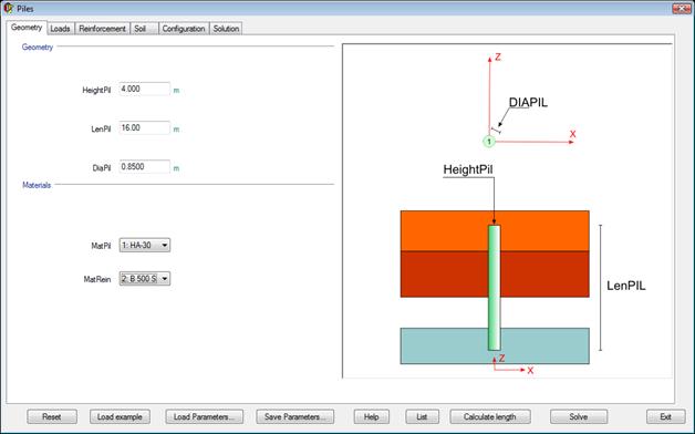
GEOMETRY
In the first window, the slab geometry is defined, number of piles, etc.
LOADS
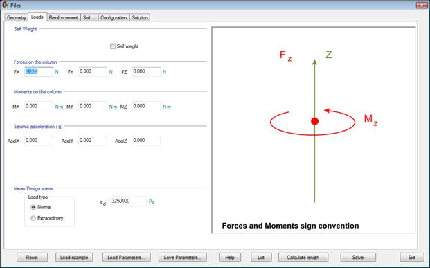
The loads on the slab are defined in the second screen (Forces and moments, type of loads, etc.).
REINFORCEMENT
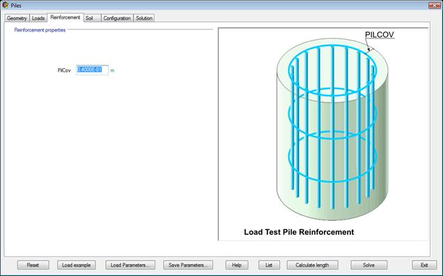
The reinforcement cover is defined in this tab.
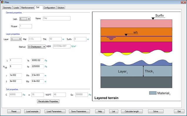
SOIL
To finish defining the model, it is necessary to select the layered terrain on which the cap is defined. A few additional parameters must also be set.
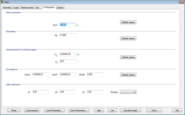
CONFIGURATION
The configuration parameters include Mesh control parameters and convergence and tolerance for the iterations.
SOLUTION
Under this tab, the design final values are shown.
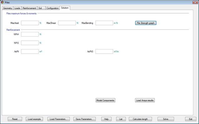
“Load Ansys results” button loads previous obtained results after pressing the Solve button.
“Pile Strength graph” button shows the pile strength graph in Ansys. It is necessary to previously load the results through the “Load Ansys results” button.
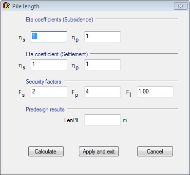
CALCULATE LENGTH
Clicking on the “Calculate length” button in the main dialog opens the CivilFEM window to predesign the pile length necessary for the chosen materials, loads and terrains.
It is possible to calculate this length as many times as needed changing the parameters in the window. Once we get the desired length we click on the Apply and exit button.
PARAMETER EXPLANATION
GEOMETRY TAB
|
HeightPil |
Head pile height. |
|
LenPil |
Pile length. |
|
DiaPil |
Pile diameter. |
|
MatPil |
Pile material. |
|
MatRein |
Reinforcement material. |
LOADS TAB
|
GammaF |
Load Factor. |
|
Fx |
X axis force. |
|
Fy |
Y axis force. |
|
Fz |
Z axis force. |
|
Mx |
X axis moment. |
|
My |
Y axis moment. |
|
Mz |
Z axis moment. |
|
AcelX |
X gravity acceleration. |
|
AcelY |
Y gravity acceleration. |
|
AcelZ |
Z gravity acceleration. |
|
|
Geotechnical/Structural pile maximum stress |
REINFORCEMENT TAB
|
PilCov |
Pile geometrical cover. |
SOIL TAB
|
General Properties and geometry: |
|
|
Ueth |
Terrain number. |
|
Name |
Terrain name. |
|
Nlayer |
Number of layers. |
|
|
|
|
Layer Properties: |
|
|
Layer |
Selected layer number. |
|
Mat |
Selected layer material. |
|
Thick |
Selected layer thickness. |
|
HeifhtT |
Terrain height. |
|
Method |
Horizontal ballast module method. |
|
HBM |
Horizontal ballast module. |
|
Group effect |
Taking or not into account group effect. |
|
l |
Cohesion coefficient if l=1 cohesive soil, if >1 cohesionless). |
|
fs |
Unitary skin friction. |
|
fs* |
Unitary skin friction with group effect. |
|
Ncb |
Bearing capacity factor. |
|
hs |
Skin subsidence group effect coefficient. |
|
fp |
Unitary point resistance. |
|
fp* |
Unitary point resistance with group effect. |
|
hp |
Point subsidence group effect coefficient. |
|
g |
Shaft deformability factor. |
|
Ws |
Skin displacement. |
|
Ws* |
Skin displacement with group effect. |
|
hs |
Skin settlement group effect coefficient. |
|
d |
Settlement factor. |
|
Wp |
Point displacement. |
|
Wp* |
Point displacement with group effect. |
|
hp |
Point settlement group effect coefficient. |
|
|
|
|
Soil Properties: |
|
|
c |
Cohesion. |
|
f |
Internal friction angle. |
|
NSPT |
Number of blows obtained in the Standard Penetration Test. |
|
|
Unconfined compressive strength. |
CONFIGURATION TAB
|
Mesh Parameters: |
|
|
DivH |
Slab horizontal division’s size. |
|
DivV |
Pile vertical division’s size. |
|
|
|
|
Parameters: |
|
|
Psi |
Et/E springs ratio. |
|
a |
Slab decrease ratio. |
|
|
|
|
Soil Parameters for cohesive graph: |
|
|
|
Cohesion limit for cohesive soils. |
|
|
Internal friction angle limit for cohesive soils. |
|
|
|
|
Convergence: |
|
|
CNVU |
Displacement convergence criterion. |
|
CNVF |
Forces convergence criterion. |
|
CNVM |
Bending moment’s convergence criterion. |
|
|
|
|
Delft Coefficients: |
|
|
a1 |
Delft passive coefficient. |
|
a2 |
Delft active coefficient. |
|
a3 |
Delft safety coefficient. |
|
|
|
|
Soil Type |
Cohesive or cohesionless. |
SOLUTION TAB
|
Piles maximum forces and moments: |
|
|
MaxAxial |
Maximum axial force. |
|
MaxShear |
Maximum shear force. |
|
MaxBending |
Maximum bending force. |
|
|
|
|
Reinforcement: |
|
|
NpiH |
Axial force limit of concrete pile. |
|
NpiS |
Axial force limit of reinforcement pile. |
|
AsPil |
Axial+Bending reinforcing steel in piles. |
|
AsPilS |
Shear reinforcing steel in piles. |
CALCULATE LENGTH
|
Eta coefficients (Subsidence) |
|
|
hs |
Subsidence Eta skin factor. |
|
hp |
Subsidence Eta point factor. |
|
Eta coefficients (Settlement) |
|
|
hs |
Settlement Eta skin factor. |
|
hp |
Settlement Eta point factor. |
|
Security Factors |
|
|
Fs |
Security skin factor. |
|
Fp |
Security point factor. |
|
Fl |
Load security factor. |
|
Predesign results |
|
|
LenPil |
Pile length calculated. |
RELATED COMMANDS:
DEFINED COMPONENTS
When solving the next components are created, the which can be browsed through the Component Manager tool of Ansys:
|
Name |
Type |
Description |
|
COLUMN_SHADOW_ |
NODE |
Nodes over which the column exerts loading in form of concentrated forces |
|
PILE_NODES_ |
NODE |
Nodes defining the piles |
|
SHELL_NODES_ |
NODE |
Nodes defining the slab |
|
H_SPRING_ |
ELEM |
Horizontal springs along the shafts of the piles |
|
V_SPRING_ |
ELEM |
Vertical springs along the shafts of the piles |
|
P_SPRING_ |
ELEM |
Point vertical springs on the piles |
|
SHELL_ELEMENTS_ |
ELEM |
Elements defining the slab |