

10-P.1 Scope
Steel structures checking according to the Steel Construction Manual of AISC 15th Edition in CivilFEM includes the checking of structures composed of welded or rolled shapes under axial forces, shear forces and bending moments in 3D.
The calculations made by CivilFEM conform to the following sections of Specifications and Codes:
|
D |
Design of members for tension. |
|
E |
Design of members for compression. |
|
F |
Design of members for flexure. |
|
G |
Design of members for shear. |
|
H |
Design of members for combined forces and torsion. |
10-P.2 Checking Types
With CivilFEM it is possible to perform the following checking and analysis types:
· Checking of sections subjected to:
|
Tension |
D |
|
Flexure |
F |
|
Shear Force |
G |
|
Flexure and axial force |
H1 |
· Buckling check:
|
Compression members subjected to flexure |
E3,E7 |
|
Compression members subjected to flexure and torsion |
E4,E7 |
10-P.3 Valid Element Types
The valid element types supported by CivilFEM are the following 2D and 3D ANSYS link and beam elements:
|
2D Link |
LINK1 |
|
3D Link |
LINK8 |
|
3D Link |
LINK10 |
|
2D Beam |
BEAM3 |
|
3D Beam |
BEAM4 |
|
3D Tapered Unsymmetrical Beam |
BEAM44 |
|
2D Tapered Elastic Unsymmetrical Beam |
BEAM54 |
|
2D Plastic Beam |
BEAM23 |
|
3D Thin-walled Beam |
BEAM24 |
|
3D Elastic Straight Pipe |
PIPE16 |
|
3D Plastic Straight Pipe |
PIPE20 |
|
3D Finite Linear Strain Beam |
BEAM188 |
|
3D Quadratic Linear Strain Beam |
BEAM189 |
Moreover, it is possible to check solid sections captured from 2D or 3D models with a transversal cross section classified as “structural steel”.
10-P.4 Valid Cross-Section Types
The steel type cross-sections used by CivilFEM can be classified as:
- All the rolled shapes (I shapes, U or channel shapes, etc.) included in the program libraries (see the hot rolled shapes library and ~SSECLIB command).
- The following welded beams: I shapes, U or channel shapes, T shapes, box, equal and unequal legs angles and pipes. (~SSECDMS commands). These sections are considered as a generic shape.
- Structural steel sections defined by plates (command ~SSECPLT). These sections are considered as a generic shape.
- Shapes from solid sections captured from 2D or 3D models which transverse cross section is classified as “structural steel” (command ~SLDSEC).
The cross-sections considered in the AISC 15TH EDITION code depend on the type of checking:
|
Checking |
Valid Cross Sections |
|
TENSION |
All. |
|
COMPRESS |
All. |
|
BENDING |
Bent about major axis: I shape, C shape with compact web, pipe shapes, box shapes and T shapes. Bent about minor axis: I shape, C shape and box shapes. |
|
SHEAR |
I, C, PIPE, ANGLE, BOX, T. |
|
BEND_AXL |
I, C shape with compact web, pipe shapes and box shapes. |
10-P.5 Data and Results used by CivilFEM
CivilFEM utilizes the following groups of data and results for checking according to AISC 15TH EDITION:
· Data concerning to sections: properties and dimensions of gross, net and effective sections, characteristics and dimensions of section plates.
· Member properties.
· Material properties.
· Forces and moments over the sections.
· Checking results.
Sections Data
AISC 15TH EDITION considers the following data set for the section:
· Gross section data
· Net section data
· Effective section data
· Data concerning to the section and plates class.
Gross section data correspond to the nominal properties of the cross-section.
From net section, only the area is considered. This area is calculated by subtracting the holes for screws, rivets and other holes from the gross section area. The user should be aware of the provisions made on section B4-3 of AISC 15TH EDITION to calculate the parameter AHOLES (the total calculated area is introduced in the parameter AHOLES with the command ~SECMDF).
The effective section data and the section and plates class data are obtained in the checking process according to chapter B, section B4 of the code. This chapter classifies steel sections into three groups (compact, noncompact and slender), depending upon the width-thickness ratio and other mandatory limits.
The AISC 15TH EDITION module utilizes the gross section data in user units and the CivilFEM axis or section axis as initial data. The program calculates the effective section data and the class data, and stores them in CivilFEM’s results file, in user units and in CivilFEM or section axis. The data can be listed and plotted with the ~PLLSSTL and ~PRSTL commands.
The section data used in AISC 15TH EDITION are shown in the following tables:
Table 5‑1 Common data for gross, net and effective sections
|
Description |
Data |
|
Input data: 1.- Height 2.- Web thickness 3.- Flanges thickness 4.- Flanges width 5.- Distance between flanges 6.- Radius of fillet (Rolled shapes) 7.- Toe radius (Rolled shapes) 8.- Weld throat thickness (Welded shapes) 9.- Web free depth |
H Tw Tf B Hi r1 r2 a d |
|
Output data |
(None) |
Table 5‑2 Gross section data
|
Description |
Data |
Reference axes |
|
Input data: 1.- Depth in Y 2.- Depth in Z 3.- Cross-section area 4.- Moments of inertia for torsion 5.- Moments of inertia for bending 6.- Product of inertia 7.- Elastic resistant modulus 8.- Plastic resistant modulus 9.- Radius of gyration 10.- Gravity center coordinates 11.- Extreme coordinates of the perimeter
12.- Distance between GC and SC in Y and in Z 13.- Warping constant 14.- Shear resistant areas 15.- Torsional resistant modulus 16.- Moments of inertia for bending about U, V 17.- Angle Y->U or Z->V |
Tky tkz A It Iyy, Izz Izy Wely, Welz Wply, Wplz iy, iz Ycdg, Zcdg Ymin, Ymax, Zmin, Zmax Yms, Zms Iw Yws, Zws Xwt Iuu, Ivv a |
CivilFEM CivilFEM
CivilFEM CivilFEM CivilFEM CivilFEM CivilFEM CivilFEM Section Section
Section
CivilFEM CivilFEM Principal CivilFEM |
|
Output data: |
(None) |
|
Table 5‑3 Net section data
|
Description |
Data |
|
Input data: 1.- Gross section area 2.- Area of holes |
Agross Aholes |
|
Output data: 1.- Cross-section area |
Anet |
* The section holes are introduced as a property at member level
The effective section depends upon the geometry of the section; thus, the effective section is calculated for each element and each of the ends of the element.
Table 5‑4 Net section data
|
Description |
Data |
|
Input data: |
(None) |
|
Output data: 1.- Effective area
|
Aeff |
Table 5‑5 Data referred to the section plates
|
Description |
Data |
|
Input data: 1.- Plates number 2.- Plate type: flange or web (for the relevant bending axis) 3.- Union condition at the ends: free or fixed 4.- Plate thickness 5.- Coordinates of the extreme points of the plate (in Section axes) |
N Pltype Cp1, Cp2 t Yp1, Yp2, Zp1, Zp2 |
|
Output data: 1.- Plate’s class 2.- Compression class 3.- Bending class 4.- Width to thickness ratio (b/t) 5.- lp compression 6.- lr compression 7.- Plate compression class 8.- lp bending 9.- lr bending 10.- Bending class |
PC CLS_COMP CLS_FLEX RATIO LAMBDP_C LAMBDR_C CLASE_C LAMBDR_P LAMBDR_F CLASE_F |
Member Properties
For AISC 15TH EDITION the checked data set used at member level is shown in the following table. All data is stored with the section data in user units and in the CivilFEM reference axis. (Parameters L, KY, KZ, KTOR, CB, LB, of ~MEMBPRO command).
Table 5‑6 Member Properties
|
Description |
Data |
|
Input data: 1.- Unbraced length of member (global buckling) 2.- Effective length factors Y direction 3.- Effective length factors Z direction 4.- Effective length factors for torsional buckling 5.- Flexural factor relative to bending moment 6.- Length between lateral restraints |
L KY KZ KTOR Cb Lb |
Material Properties
For AISC 15TH EDITION checking, the following material properties are used:
Table 5‑7 Material properties
|
Description |
Property |
|
Steel yield strength |
Fy(th) |
|
Ultimate strength |
Fu(th) |
|
Elasticity modulus |
E |
|
Poisson coefficient |
n |
|
Shear modulus |
G |
10-P.6 Checking Process
Necessary steps to conduct the different checks in CivilFEM are as follows:
a)
Obtain material properties corresponding to the
element stored in CivilFEM database and calculate the rest of the properties
needed for checking:
Properties obtained from CivilFEM database: (command ~CFMP)
|
Elasticity modulus |
E |
|
Poisson’s ratio |
n |
|
Yield strength |
Fy (th) |
|
Ultimate strength |
Fu (th) |
|
Shear modulus |
G |
|
Thickness of corresponding plate |
th |
b) Obtain the cross-sectional data corresponding to the element.
c) Initiate the values of the plate’s reduction factors and the other plate’s parameters to determine its class.
d) Perform a check of the section according to the type of external load.
e) Results. In CivilFEM, checking results for each element end are grouped into alternatives in the results file .RCV, so that the user may access them by indicating the number of the alternative using the CivilFEM command ~CFSET.
The required data for the different checking types are provided within tables found in their corresponding section of this manual.
Design Requirements.
Design for Strength Using Load and Resistance Factor Design (LRFD)
Design shall be performed in accordance with:

Where:
|
|
Required strength (LRFD). |
|
|
Nominal strength. |
|
|
Resistance factor. |
|
|
Design strength |


Design for Strength Using Allowable Strength Design (ASD)
Design shall be performed in accordance with:

Where:
|
Ra |
Required strength (ASD) |
|
Rn |
Nominal strength. |
|
Ω |
Safety factor |
|
Rn/ Ω |
Allowable strength |
General Processing of Sections. Section Class.
Steel sections
are classified as compact, noncompact or slender-element sections for bending
sections and slender or non slender for compression sections. For a section to
qualify as compact its flanges must be continuously connected to the web or webs
and the width-thickness ratios of its compression elements must not exceed the
limiting width-thickness ratios  (see table B4.1 of AISC 15TH EDITION). If the width-thickness ratio
of one or more compression elements exceeds but does not exceed
(see table B4.1 of AISC 15TH EDITION). If the width-thickness ratio
of one or more compression elements exceeds but does not exceed  , the section is noncompact. If the width-thickness ratio of any
element exceeds , (see table B4.1 of AISC 15TH EDITION), the section is referred to
as a slender-element compression section.
, the section is noncompact. If the width-thickness ratio of any
element exceeds , (see table B4.1 of AISC 15TH EDITION), the section is referred to
as a slender-element compression section.
Therefore, the code suggests different lambda values depending on if the element is subjected to compression, flexure or compression plus flexure.
The section classification is the worst-case scenario of all of its plates. Therefore, the class is calculated for each plate with the exception of pipe sections, which have their own formulation because it cannot be decomposed into plates. This classification will consider the following parameters:
a) Length of elements:
The program will define the element length (b or h) as the length of the plate (distance between the extreme points), except when otherwise specified.
b) Flange or web distinction:
To distinguish between flanges or webs, the program follows the criteria below:
Once the principal axis of bending is defined, the program will
examine the plates of the section. Fields Pty and Ptz of the plates indicate if
they behave as flanges, webs or undefined, choosing the correct one for the
each axis. If undefined, the following criterion will be used to classify the
plate as flange or web: if  (increments of end coordinates) and flexure is in the Y axis, it
will be considered a web; if not, it will be a flange. The reverse will hold
true for flexure in the Z-axis.
(increments of end coordinates) and flexure is in the Y axis, it
will be considered a web; if not, it will be a flange. The reverse will hold
true for flexure in the Z-axis.
· Steel Shapes dimensions:
Section I and C:
The length of the plate h will be taken as the value d for the section dimensions.
Rectangular HSS:
The length of the plate will be taken as the width length minus three times the design thickness (=0.93*nominal thickness).
Box by dimensions:
The length of the plate will be taken as the width length minus two times the thickness.
Round HSS:
The length of the plate will be taken as the external diameter. Thickness will be taken as the design thickness (=0.93*nominal thickness).
Pipe by dimensions:
The length of the plate will be taken as the external diameter. Thickness will be taken as the thickness of the section.
Members Subjected to Compression
In order to check for compression it is necessary to determine if the element is stiffened or unstiffened.

Pipe sections

Box sections

- Unstiffened elements:

Angular sections

Stem of T sections

Members Subjected to Bending
The bending check is only applicable to very specific sections. Therefore, the slenderness factor is listed for each section:
· Section I and C:
Flanges of rolled sections:


Flanges of welded sections:

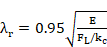

 = 0.7Fyf.
Web:
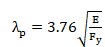

· Pipe section:


· Box section:
Flanges of box section:

Flanges: the program distinguishes between the flange and web upon the principal axis chosen by the user.

· T section:
Stem:


Flanges:

Checking of Members for Tension (Chapter D)
The axial tension force must be taken as positive (if the tension force has a negative value, the element will not be checked)
Design tensile
strength  and the allowable tensile strength
  , of tension members, shall be the lower
value of :
, of tension members, shall be the lower
value of :
a) yielding in the gross section:

b) rupture in the net section:

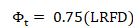
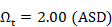
Being:
|
|
Effective net area. |
|
|
Gross area. |
|
|
Minimum yield stress. |
|
|
Minimum tensile strength. |


The effective net area will be taken from the net section properties (by default as Ag – AHOLES). It is important to notice that the shear leg factor U is not included so the user must modify the default effective net area Aeff =(Ag – AHOLES)*U. Net section properties can be modified using the command ~SECMDF.
Checking of Members in Axial Compression (Chapter E)
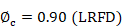
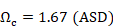
The design
compressive strength,  , and the allowable compressive strength,
  , are determined as follows:
The nominal
compressive strength,  , shall be the lowest value obtained according to the limit states
of flexural buckling and flexural-torsional buckling.
, shall be the lowest value obtained according to the limit states
of flexural buckling and flexural-torsional buckling.
Nominal compressive strength, :
 (E3-1)
(a) If 
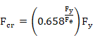
(b) If 
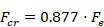
Compressive Strength for Flexural Buckling
Calculation of elastic critical buckling stress is performed for each axis and is calculated as the lowest of both:
This type of check can be carried out for compact sections as well as for noncompact or slender sections. These three cases adhere to the following steps:
The value Fe will be taken as the minimum of Fe for flexural buckling (about both axis) and Fe for flexural-torsional buckling.
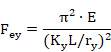
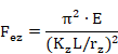
Where:
|
r |
Governing radius of gyration about the buckling axis. |
|
K |
Effective length factor. |
|
L |
Unbraced length. |
Compressive Strength for Flexural-Torsional Buckling
The elastic stress for critical torsional buckling or flexural-torsional buckling Fe is calculated as:
I shape sections:
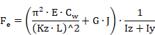
T shape sections:
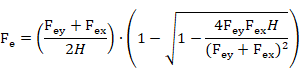
C shape sections:
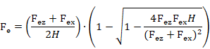
Other sections: the lowest root of the following third degree equation, in which the axis have been changed to adapt to the CivilFEM normal axis:
 (E4-4)
Where:
|
|
Effective length factor for torsional buckling. |
|
G |
Shear modulus (MPa). |
|
|
Warping constant (mm6). |
|
J |
Torsional constant (mm4). |
|
|
Moments of inertia about the principal axis (mm4). |
|
|
Coordinates of shear center with respect to the center of gravity (mm). |


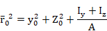
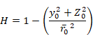


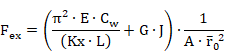
where:
|
A |
Cross-sectional area of member. |
|
L |
Unbraced length. |
|
|
Effective length factor, in the z and y directions. |
|
|
Radii of gyration about the principal axes. |
|
|
Polar radius of gyration about the shear center. |


In this formula, CivilFEM principal axes are used. If the CivilFEM axes are the principal axes ±5º sexagesimal degrees, Ky and Kz are calculated with respect to the Y and Z-axes of CivilFEM. If this is not the case (angular shapes, for example) axes U and V will be used as principal axes, with U as the axis with higher inertia.
The torsional inertia (Ixx in CivilFEM, J in AISC 15TH EDITION) is calculated for CivilFEM sections, but not for captured sections. Therefore the user will have to introduce this parameter in the mechanical properties of CivilFEM.
Output results are written in the CivilFEM results file (.RCV) as an alternative.
Checking of Members for Flexure (Chapter F)
Chapter F is only applicable to members subject to simple bending about one principal axis.
The design flexural strength, , and the allowable flexural strength,
  , shall be determined as follows:
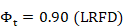
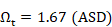
For all provisions: = 0.90 (LRFD)
  = 1.67 (ASD)
Where Mn is the lowest value of four checks according to sections of chapter F:
a) Yielding
b) Lateral-torsional buckling
c) Flange local buckling
d) Web local buckling
The value of the nominal flexural strength with the following considerations:
Shape: I-shaped members and channels
bent about their major axis with compact web 

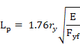
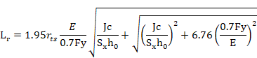
Limit state:
· Yielding:
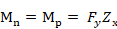
· LTB (Lp<Lb<=Lr):

· LTB (Lb>Lr):
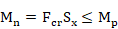
 = Value introduced by user in member properties
 = Critical
stress
= Critical
stress
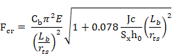
 = = elastic section modulus
 = distance between the flange centroids
· FLB (noncompact flanges):

· FLB (slender flanges):
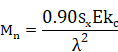

Shape: I-shaped members bent about their
major axis with noncompact web.
Limit state:
· Yielding:


 = elastic section modulus referred to
compression flange
= elastic section modulus referred to
compression flange
 = web plastification factor, determined in
accordance with Section F4.2(c)(6)
= web plastification factor, determined in
accordance with Section F4.2(c)(6)
· LTB (Lp<Lb<=Lr):

· LTB (Lb>Lr):

= Value introduced by user in member properties
= Critical
stress
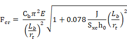
= web plastification factor
· FLB (noncompact flanges):

· FLB (slender flanges):
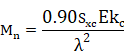
Shape: I-shaped members bent about their
major axis with slender web.
Limit state:
· Yielding:

= elastic section modulus referred to
compression flange
 = Bending strength reduction factor (F5-6)
· LTB (Lp<Lb<=Lr):

· LTB (Lb>Lr):
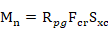
= Value introduced by user in member properties
= Critical
stress
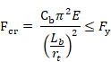
= Bending strength reduction factor (F5-6)
· FLB (noncompact flanges):
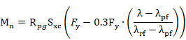
· FLB (slender flanges):
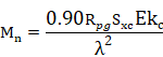
Shape: I-shaped members and channels
bent about their minor axis. 

Limit state:
· Yielding:

· FLB (noncompact flanges):

· FLB (slender flanges):
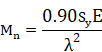
Shape: Box. 
Limit state:
· Yielding:
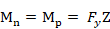
· LTB (Lp<Lb<=Lr):

· LTB (Lb>Lr):
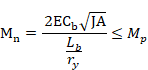
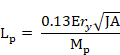

· FLB (noncompact flanges):
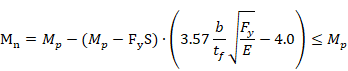
· FLB (slender flanges):

 = effective section modulus determined with
the effective width, be, of the compression flange (F7-4 o F7-5)
= effective section modulus determined with
the effective width, be, of the compression flange (F7-4 o F7-5)
· WLB (noncompact web):

· WLB (slender web): Value is taken as the lowest for compression flange yielding (F7-7) and compression flange local buckling (F7-8)
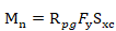
= elastic section modulus referred to
compression flange
= Bending strength reduction factor (F5-6)

Shape: Tubular
Limit state:
· Yielding:
· FLB (noncompact):
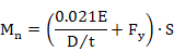
· FLB (slender):

Shape:Tees
loaded in the plane of symmetry
Estado Límite:
· Yielding (tee stems in tension):

· Yielding (tee stem in compression):

· LTB (Lp<Lb<=Lr):
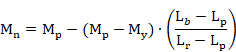
· LTB (Lb>Lr):
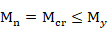
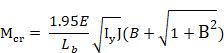
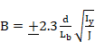
(positive sign if the stem is under tension, negative if it is under compression)
Output results are written in the CivilFEM results file (.RCV) as an alternative.
Checking of Members for Shear (Chapter G)
The design shear
strength,  , and the allowable shear strength,
  , shall be determined as follows:
For all
provisions:  = 0.90 (LRFD)
  = 1.67 (ASD)
Except for webs of rolled I-shaped members with  .
.
In this case: = 1.00 (LRFD) = 1.50 (ASD)
According to the
limit states of shear yielding and shear buckling, the nominal shear strength,  , is calculated following the next
considerations:
, is calculated following the next
considerations:
Shape: I-shaped and Channels with shear
forcé in the web plane.
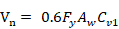
For
webs of rolled I-shaped members with -> 
For all other I-shaped members and channels:
If 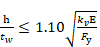 ->
->
If 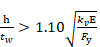 ->
-> 
It is assumed that there are no stiffeners;
therefore, the web plate buckling coefficient  will be calculated as a constant equal to 5.34.
Shape: Tubular

Because the Lv value (distance from maximum cutting force to zero) is unknown, Fcr is calculated as:
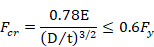
Shape: Other sections
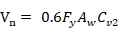
 y
y is calculated following chapters G3,G4 y G6
Output results are written in the CivilFEM results file (.RCV) as an alternative.
Checking of Members for Combined Forces and Torsion (Chapter H)
Checking of Members Subject to Flexure and Axial Tension / Compression
For this check, it is first necessary to
determine the value of Mn. This value comes into play in the checking of
formulas. The value of Mn, will be calculated in the same way as members
subjected to flexure; thus, the nominal flexure strength ( ) is the minimum of four checks:
1. Yielding
2. Lateral-torsional buckling
3. Flange local buckling
4. Web local buckling
In the case of having bending plus tension or bending plus compression, the interaction between flexure and axial force is limited by the following equations:
(a) For 
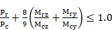 (H1-1a)
(b) For 
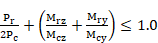 (H1-1b)
If the axial force is tension:
|
|
Required tensile strength (N). |
|
|
Available tensile strength (N):
|
|
|
Required flexural strength (N·mm). |
|
|
Available flexural strength (N·mm): Design: Allowable: |
|
y |
Strong axis bending. |
|
z |
Weak axis bending. |
|
|
Resistance factor for tension (Sect.D2) |
|
|
Resistance factor for flexure = 0.90 |
|
|
Safety factor for tension (Sect D2) |
|
|
Safety factor for flexure = 1.67 |


If the axial force is compression:
|
|
Required compressive strength (N). |
|
|
Available compressive strength (N): Design: Allowable: |
|
|
Required flexural strength (N·mm). |
|
|
Available flexural strength (N·mm): Design: Allowable: |
|
Y |
Strong axis of bending. |
|
Z |
Weak axis of bending. |
|
|
Resistance factor for compression =0.90 |
|
|
Resistance factor for flexure = 0.90 |
|
|
Safety factor for compression =1.67 |
|
|
Safety factor for flexure = 1.67 |


The following checks are carried out by CivilFEM:
- Axial force and flexural buckling
- Bending moment Z direction
- Bending moment Y direction
If one of these checks do not meet the code requirements, it will not be possible to check the member under flexure plus tension / compression.
Output results are written in the CivilFEM results file (.RCV) as an alternative.