10-B.1 Scope
For checking steel structures according to EA in CivilFEM, it is possible to check steel structures made of rolled or welded shapes. The calculations are performed according to the design recommendations included in articles 3.1, 3.2 and 3.4 of the EA Code.
Cross sections available for checking are those accessible by the library as well as by sections created by dimensions or plates. Solid sections made by structural steel are also acceptable for checking.
10-B.2 Calculation Basis
10-B.2.1 Design Steel Strength
The design steel strength su is obtained from the material yield strength se and from its partial safety factor ga, according to the prescriptions included in the article 3.1.7. of the EA Code:

where:
|
|
steel yield strength |
|
|
partial safety factor |

Both the steel yield strength se and the partial safety factor ga should be previously defined in the material properties associated to each element. (See ~CFMP command).
10-B.2.2 Section Data
The section data of the element must be included in CivilFEM database. All geometrical and mechanical properties are automatically obtained defining the cross section or capturing the solid section. Below the section data necessary for checking according to EA are listed:
Table 10-B.2‑1 Section Data
|
Data |
Description |
|
A |
Area of the cross-section |
|
|
Moment of inertia about Y axis |
|
|
Moment of inertia about Z axis |
|
|
Product of inertia about YZ |
|
Y |
Coordinate Y of the considered fiber |
|
Z |
Coordinate Z of the considered fiber |
|
|
Radius of gyration about Y axis |
|
|
Radius of gyration about Z axis |
|
|
Shear area in Y |
|
|
Shear area in Z |
|
|
Torsional modulus |


10-B.2.3 Forces and Moments
Forces and moments for element’s ends are obtained from CivilFEM’s results file (file. RCV) for the selected load step and substep.
Table 10-B.2‑2 Forces and Moments
|
Forces and Moments |
Description |
|
|
Axial force. |
|
|
Design Shear force in Y. |
|
|
Design Shear force in Z. |
|
|
Design torsional moment. |
|
|
Bending moment in Y. |
|
|
Bending moment in Z. |


10-B.2.4 Maximum Member Slenderness Calculation
The mechanic slenderness of the member in both planes is calculated from the unbraced length of the member L, the buckling length factors in both planes bXY and bXZ, (see ~MEMBPRO command), and from the radius of gyration of the section iy and iz. Finally, the maximum slenderness is adopted:


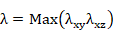
The values of the parameters BETAXY and BETAXZ are defined in the articles 3.2.4 of the code.
In non symmetric sections the slenderness values are taken about the axis corresponding to the inertia principal directions u, v.


where:
|
u |
principal axis of inertia |
|
v |
secondary axis of inertia |
10-B.2.5 Calculation of the Buckling Factor w
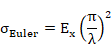
The  coefficient is obtained from the modulus of elasticity Ex, the
steel yield strength
coefficient is obtained from the modulus of elasticity Ex, the
steel yield strength  , ( is taken as the maximum of the plates), and from the maximum
slenderness of the member 𝜆, using the following
formulation:
, ( is taken as the maximum of the plates), and from the maximum
slenderness of the member 𝜆, using the following
formulation:
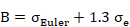
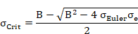

For each element, the calculated value is stored as an alternative in CivilFEM’s results file (file.RCV)
with the parameter name OMEGA.
10-B.3 Compression Check
In CivilFEM, checking elements under compression according to EA is done for both end sections (I- and J-sections) of those elements of the model or solid sections a cross section type of structural steel.
10-B.3.1 Checking for Buckling of Members Subjected to Axial Compression
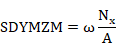
The axial direct stress is calculated as the product of the axial compressive force acting on the section and the buckling factor w (as calculated above), divided by the area of the section. This value is stored for each element end in the active alternative in CivilFEM’s results file with the parameter name SDYMZM.
10-B.3.2 Checking for Buckling of Members Subjected to Axial Force + Bending Moment
The combined stresses due to the axial compression force and bending moments around the Y and Z axes are calculated from force and moment values, stresses at every point of the section and mechanical properties of the section, with the buckling factor w:

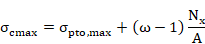
 is the stress corresponding to the point of maximum stress
  .
.
As calculated above, the maximum combined stress, for each element end is stored in the active alternative in CivilFEM’s results file with the parameter name SCMAX.
10-B.3.3 Calculation of the Maximum Equivalent Stress in the Section
The maximum
equivalent stress in this section,  , is taken as the value of the maximum combined stress
  , calculated in the previous section:

The maximum equivalent stress for each element end is stored in the active alternative in CivilFEM’s results file with the parameter name SCEQV.
10-B.3.4 Calculation of EA Criterion
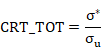
The calculated equivalent stress is then divided by the steel design strength su in order to obtain a value that is stored as the CRT_TOT parameter in CivilFEM’s results file for each element end. This value shall be between 0.0 and 1.0 in for the element to be valid according to the EA code; therefore, the equivalent stress must be lower than the steel design stress.
10-B.4 Tension Check
In CivilFEM, checking of elements under tension according to EA code is done for each element end of those selected elements or solid sections in the model with a cross section type of structural steel.
10-B.4.1 Calculation of the Net Section Area
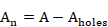
The net section area is calculated by subtracting the area of the holes (AHOLES parameter of the ~SECMDF command) from the gross area:
10-B.4.2 Checking of Members Subjected to Tension
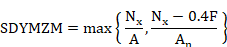
The stress due to the axial tension force is calculated as the greater of the following values:
· The quotient between the axial tension force acting on the section, Nx, and the area of the section.
· The quotient with a nominator of the axial tension force acting on the section subtracted by the sum of the forces transmitted by the bolts from the net section, F, multiplied by 0.4 and a denominator of the net section area.
This value is stored in the active alternative in CivilFEM’s results file with the parameter named SDYMZM:
10-B.4.3 Checking of Members Subjected to Bending Moment + Axial Tension
The combined stresses due to an axial tension force and bending moments about the Y and Z axes are calculated from forces and moments values, stresses in every point of the section and mechanical properties of the section. These stresses also take into account the net section area and the sum of the forces and moments transmitted by the bolts located in the net section:

Where is the stress corresponding to the point of maximum stress .
The maximum combined stress calculated as above for each element end is stored in the active alternative in CivilFEM’s results file with the parameter named SCMAX.
10-B.4.4 Calculation of the Maximum Equivalent Stress in the Section
The maximum
equivalent stress in this section,  , is taken as the value of the maximum combined stress
  , calculated in the previous section:

The maximum equivalent stress for each element end is stored in the active alternative in CivilFEM’s results file with the parameter named SCEQV.
10-B.4.5 Calculation of EA Criterion
The equivalent stress obtained is then divided by the steel design strength su in order to obtain a value that is stored as the CRT_TOT parameter in CivilFEM’s results file for each element end. This value shall be between 0.0 and 1.0 in order for the element to be valid according to the EA code; consequently, the equivalent stress must be lower than the steel design stress.
10-B.5 Bending Check
In CivilFEM the checking of elements under bending according to EA code is done for each element end of those selected elements or solid sections of the model whose cross section type is structural steel. For the checking, the program follows the following steps:
10-B.5.1 Calculation of Maximum Combined Stress
The combined stresses due to an axial force and bending moments about the Y and Z axes are calculated from stresses in every of the point of the section and mechanical properties of the section.
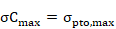
Where is the stress corresponding to the point of maximum stress .
The maximum combined stress as calculated above for each element end is stored in the active alternative in CivilFEM’s results file with the parameter named SCMAX.
10-B.5.2 Calculation of the Maximum Tangential Stress
The maximum tangential shear and torsion stresses for each element end are calculated from the shear forces and torsional moments and the sectional mechanical properties in the following equations:


where:
|
|
Maximum
tangential stress due to the shear force |
|
|
Maximum
tangential stress due to the shear force |
|
|
Shear area about Y axis. |
|
|
Shear area about Z axis. |
|
|
Maximum tangential stress due to torsion. |
|
|
Torsional resistant modulus. |


The maximum tangential stress is taken as the maximum of the sum of the maximum tangential stresses due to the torsional moment and the maximum tangential stress due to the shear force for the Y and Z axes directions:

The maximum tangential stress for each element end is stored in the active alternative in CivilFEM’s results file with the parameter named SSMAX.
10-B.5.3 Calculation of the Maximum Equivalent Stress in the Section
The equivalent stress s* is calculated according to the specifications stated in the article 3.4.3.5 of the code, through the following expression:
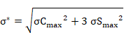
The maximum equivalent stress for each element end is stored in the active alternative in CivilFEM’s results file with the parameter named SCEQV.
10-B.5.4 Calculation of the EA Criterion
The equivalent stress obtained is then divided by the steel design strength su in order to obtain a value that is stored as the CRT_TOT parameter in the active alternative in CivilFEM’s results file for each element end. This value shall be between 0.0 and 1.0 in order for the element to be valid according to the EA code; thus, the equivalent stress must be lower than the steel design stress.