

Cross Sections Explorer
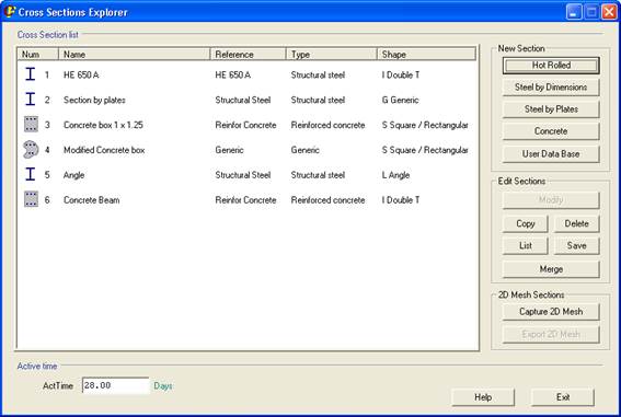
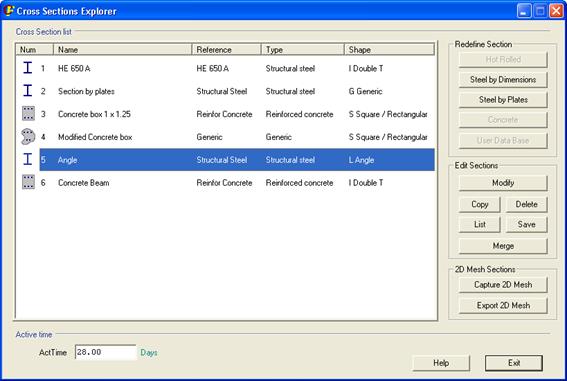
In the sections window there is a list with the sections already created.
New sections can be created in this section by using the set of buttons grouped under the title New Section. These options correspond to the following commands according to the type of section:
- ~SSECLIB – Hot Rolled
- ~SSECDMS – Steel by Dimensions
- ~SSECPLT – Steel by Plates
- ~CSECDMS – Concrete
- ~CSLIB –User Data Base
The title Edit Sections contains the following functions: Delete (~CSDEL command), Modify (~SECMDF command ), Copy (~CSGEN command), List the existing sections (~CSLST command), Save the created sections (~CSLIB command) or Merge two existing sections to create a new one (~CSMRG command).
It is also possible to export sections as meshed sections (Export 2D Mesh, ~SEC2DOU command ) or import them (Capture 2D Mesh, ~SEC2DIN command )
General Utilities
It is possible to open an utilities menu, by right clicking on the graphic screen.
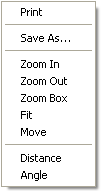
- Print: Prints the current view.
- Save As…: Saves the current view as a Windows Bitmap file (BMP).
- Zoom In: A zoom of the section is done. The center of the image is the point where the right click was done.
- Zoom Out: A zoom out of the section will be done.
- Zoom Box: A box can be created by clicking the two corners of it on the screen. A zoom will be done to this box.
- Fit: The initial view of the section is displayed, showing the complete extents of it.
- Move: The graphics shown in the window can be panned with this utility.
- Distance: The distance between two points is calculated by clicking on the desired two points of the screen. The result will be shown on the lower bar of the window. An automatic snap will be done to the characteristic points of the section.
- Angle: The angle between two segments is calculated by clicking on the three points of the screen which define the segments. The result will be shown on the lower bar of the window. An automatic snap will be done to the characteristic points of the section.
Section generation
The generation of the different types of sections is illustrated hereafter.
Hot Rolled steel sections
To select the desired section, the user must find the section in the shapes library, located in the left side of the window. This library contains all the shapes classified in CivilFEM.
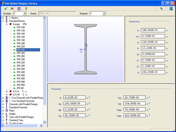
In the top right corner of the window, the user may find the Search button (Find). This icon displays a window in which sections may be found from the properties specified by the user.
The search utility can also be displayed by clicking with the right button on the sections tree (left hand side of the screen).
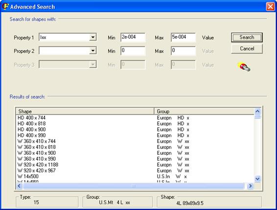
Up to three properties with minimum and maximum values for each property can be selected.
If the section library needed is not included in the standard CivilFEM collection, it is possible to introduce it and save it for future uses (Add Shape button).
Steel by Dimensions
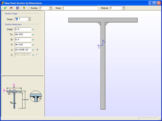
In this window, steel sections by dimensions may be created. To do so, the type of section must be previously selected. The different type of sections supported by CivilFEM are the following:
- I
- C
- T
- L
- PIPE
- BOX
After defining the type of section, the desired values are introduced in the corresponding boxes. To identify the notation used in the section’s geometry, the user may consult the figure attached in the bottom left corner of the screen.
Steel by Plates
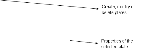
Steel sections may also be defined by plates. To do so, the user must choose the option Steel by Plates and then create each of the plates conforming the section. Clicking on the New plate button, the user will create a new plate, and by clicking the Modify plate button the user will be able to modify properties of the existing plate. The Delete plate button will delete plates.
If the user clicks onto one of the plates with the mouse, the corresponding plate will change the colour and its properties will be displayed in the window.
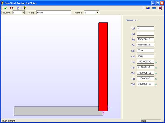
When creating or modifying a plate, the following window will be displayed.
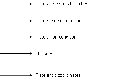
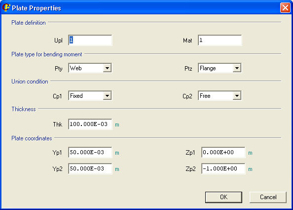
To create the plate it will be necessary to fill out all the values.
If an existing plate is modified, it will not be possible to change the plate number (Upl).
Concrete by Dimensions
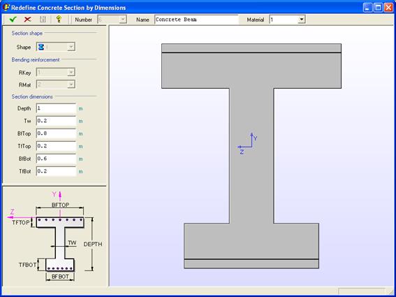
In this screen, concrete sections may be created by dimensions. To do so, the type of section must be selected (Shape). Possible section types are:
- I
- C
- T
- L
- PIPE
- BOX
After defining the section type, the desired values must be introduced in the corresponding boxes. To identify the notation used in the section’s geometry, the user may consult the figure attached in the bottom left corner of the screen.
It is possible to define a preliminary reinforcement in CivilFEM by activating the Rkey option. Depending on the type of section, the Rkey field will have different values. The reinforcement material is determined in the Rmat field.
User Data Base
It is possible to use a section defined in a previous session if it has been saved.
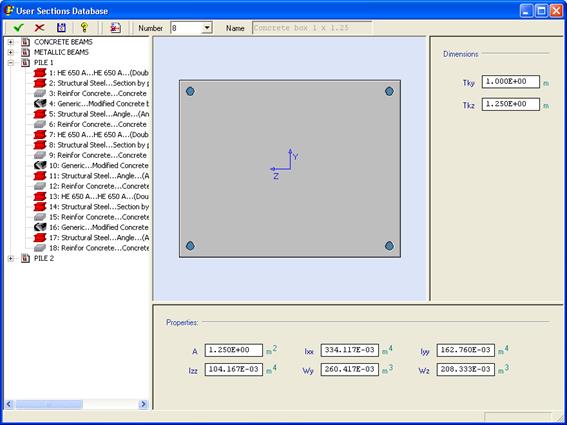
CivilFEM automatically loads all the saved sections. These user defined sections are displayed in a tree form, showing each of the files created and the sections it contains.
It is possible to delete a section from a file by simply clicking on the button Delete.
Complete files can also be deleted, selecting the name of the file on the tree and pressing the button Delete.
On the upper part of the window the user can select the identification number of the loaded section (Number field).
The files created are located in the folder ShapeLib\CSLib and have a .UCS extension. To use the saved sections in a different computer, it is only necessary to copy the file or files that contain the sections to the respective folder on the other computer.
Sections Redefinition
Once the section has been created, if necessary, any characteristic of the section may be redefined. To do so, the user must select the desired section. Once it is selected, the group of buttons New Section will transform to Redefine Section, and clicking on any of them will display the window corresponding to the type section. Therefore, it is possible to transform a section easily (for example, the user may convert a steel section from the library onto a steel section by plates).
Modification of Sections
It is possible to modify an existing section. To do so, the user must select the Cross Sections Explorer and press the Modify button.
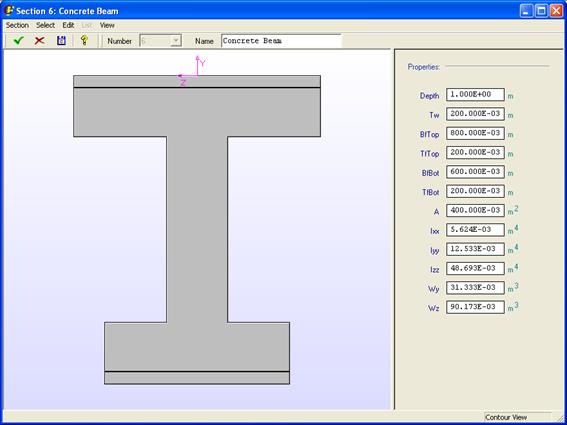
In this window, a representation of the section may be found. In this representation, the user may select with a click of the mouse some of the section’s components (tessellas, points, reinforcement groups, etc.) and its Properties will be displayed in the right hand side of the screen. The selection is carried out with the mouse pointer, clicking with the left button. To interchange between select (arrow pointing upwards) and unselect (arrow pointing downwards) modes, the user must press the mouse right button (see menu Edit).
The different possibilities of section modifications are explained hereafter:
Section Menu
The only option available in this version of CivilFEM is existing the modification utility, without saving the changes carried out by the user (Quit). It is equivalent to the Cancel button in the tool bar menu.
Select Menu
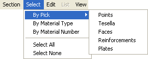
In this menu, subgroups of the selected data can be chosen. The selection may be carried out with the mouse pointer (By Pick), by Material Type or by Material Number.
If the selected option is By Pick, CivilFEM will provide the user with the possible section’s alternatives from which to choose:
- Points
- Tesella
- Faces
- Reinforcements
- Plates
All the elements can also be selected (Select All) or deselected (Select None) at once.
Edit Menu
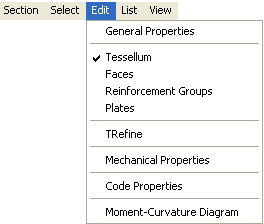
In this menu the user may access the section’s properties edition. The menu has six sections.
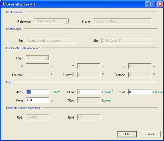
§ General Properties. Here, the user may modify some of the most generic section properties.
§ Tesselum, Faces, Reinforcement Groups and Plates. CivilFEM allows:
- To Change the Material of the tessella
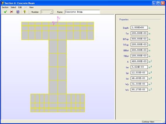
- Create, Delete or Modify section’s faces
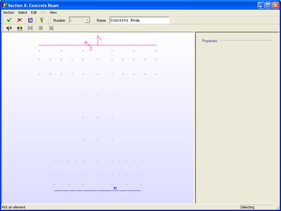
- Create, Delete or Modify section’s reinforcement groups
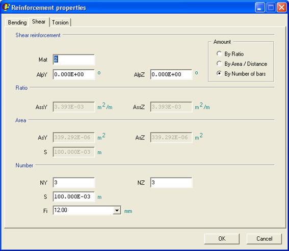
- Create, Delete or Modify section’s plates.
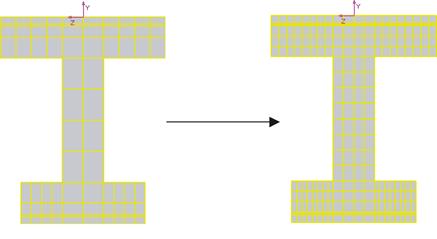
§ Refining Tessella (TRefine). This option allows to increment the number of tessella that form the section (remeshing the section) to obtain more precise results in the calculations carried out (command ~TREFINE ). The option modify tessella must be active (Edit -> Tessellum).
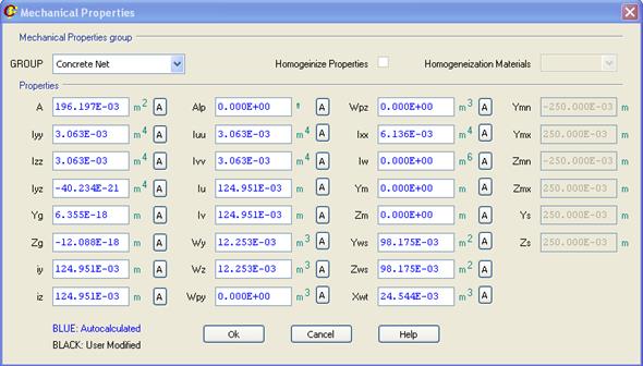
§ Mechanical Properties. CivilFEM allows the section properties to be changed just by entering the value in the corresponding edit box. The original value can be retrieved again by clicking on the A button (autocalculate).
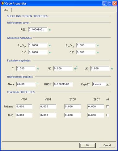
§ Code Properties. In this window, the user may change properties of the active code.
§ Moment-Curvature Diagram. This option can be activated with the Non Linear Concrete Module. In this window, the user may define a moment-curvature diagram for the section, calculate the theoretical diagram or modify the existing diagram (command ~SECMDF ).
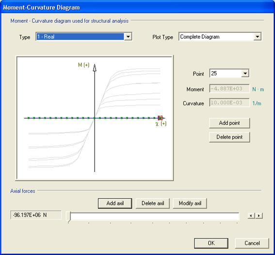
Each branch of the diagram corresponds to a different axial load. The introduced axial load values may be modified (Modify axial load) or Deleted (Delete axial load). The user may also insert a new value (Add axial load). Each branch is formed by points. Each point corresponds to a value of the bending moment and curvature concomitant with the axial load that cracks the section for the branch where they belong. These points may also be deleted (Delete point), created (Add point) or modified (introducing the new values in the field (Moment and Curvature).
List Menu
This option is not available in this CivilFEM version
View Menu
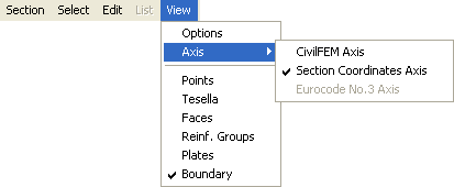
In this menu, the user may select the section visualization options.
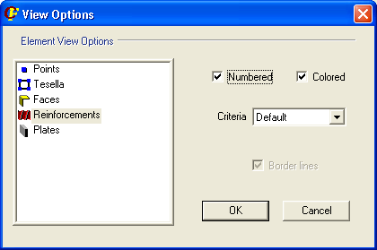
§ Options. The user may select how to display the elements (points, tessella, faces, reinforcement and plates): numbering, colours, criteria to follow and border lines.
§ Axis. Axis system that is going to be represented.
§ Elements to represent (Points, Tesella, Faces, Reinf. Groups, Plates, Boundary)
Save Sections
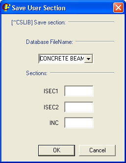
It is posible to save the created sections to use them in future sessions of CivilFEM. By pressing the Save button (~CSLIB command) on the section browser window, a dialog will appear.
In this dialog the user must specify the name of the file the sections will be included in, and the sections that will be saved.
Section Merge
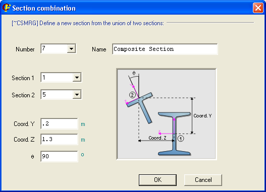
Occasionally it is necessary to create a section as a composition of two existing sections. This is performed with the Merge utility, which can be accessed by pressing the Merge button on the section browser window (~CSMRG command).
In the Merge dialog, the following data must be entered:
- Number: New section Id number.
- Section 1: First section.
- Section 2: Second section.
- Coord. Y: Y coordinate of the axis origin of section 2 (referred to the axis of section 1).
- Coord. Z: Z coordinate of the axis origin of section 2 (referred to the axis of section 1).
- q: Rotation angle of section 2, measured counterclockwise from the vertical line.
- Name: Name of the new section.
The created section will maintain all the properties of section 1 and it will have all the points, tessella, faces, plates, reinforcement groups, etc. of the two initial sections.
The merged section cannot have tessella of one section on top of tessella of the other, although it can have plates over tessella.
Related commands: