Chapter 6
CivilFEM Combinations
6.1 CivilFEM Combinations
Through the CivilFEM the combinations module, the user can select a set of load cases and combine them in such a way to achieve targeted results. Therefore, the results combination is based on the search for a specific combination among a certain data set which adheres to a particular set of rules which will solve for the targets at every node of the system.
The combinations module can be used to solve problems such as the following example:
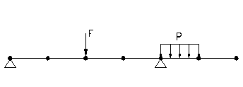
Figure 6.1-1
As the figure illustrates, a beam with two supports is divided into elements and submitted to the actions of:
· A vertical force F that can be placed at any node (but only one at any moment)
· A uniform distributed load P that can act on any of the indicated elements (All, several, one, or none of them).
The objective is to search for the load distribution that will produce the most unfavorable load case using every node and element of the system. This load case will be used to calculate a target criterion, for example the maximum bending moment MZ. In this example, the worst load case will be found by determining where the force F (at which node) and the distributed load (on which element or elements) should be placed in order to obtain the maximum bending moment MZ. Once this value is calculated, the remaining forces and moments (FX, FY, FZ, MX and MY) that are obtained on the same node and with the same loads configuration are the designated as concomitant values.
Moreover, the vertical force F and the uniform distributed load P can be modified by variable factors that will increase or decrease their effect to achieve the most unfavorable case, as is common in code checks.
Other problem types that can be solved by the combinations module may be found in the Examples Manual.
Apart from using CivilFEM combination capabilities to obtain a desired target value, it is possible to obtain the results from every load case generated from the defined combination rules (command ~LINCMB). This chapter focuses on utilizing the module to find a target value. Chapter 6.10 explains the differences between searching for a target and obtaining all the possible load case results.
6.2 Results Combination in ANSYS and in CivilFEM
The result combinations with ANSYS allow the user to utilize different result sets in an explicit way (Load Case). The user must define which result sets should be used and how they should be combined to obtain the desired result. The load case used to obtain the result will be the same for the whole model. Therefore, an example of an ANSYS load case would be the following:
“LoadCase1 = 1.20 * LoadStep1 + 0.95 * LoadStep3”
However, in CivilFEM, a combination rule can be defined in an implicit way. To be precise, the user can indicate which result sets or start states and what rules will be utilized in the combination. This combination will differ from the example above in that it will obtain certain targets or criteria for each node of the model. Therefore, it is possible to define a combination rule as:
Combination1 = Add two load cases chosen between [ (1.20 or 0.95) * LoadStep1, (0.95 or 0.00) * LoadStep2, (0.95 or 0.75) * LoadStep3 ]
Logically, the previously definition for combination1 allows 12 possibilities:
Combination1 = 1.20 * LoadStep1 + 0.95 * LoadStep2
Combination1 = 1.20 * LoadStep1 + 0.95 * LoadStep3
Combination1 = 0.95 * LoadStep2 + 0.95 * LoadStep3
Combination1 = 0.95 * LoadStep1 + 0.95 * LoadStep2
Combination1 = 0.95 * LoadStep1 + 0.95 * LoadStep3
Combination1 = 0.00 * LoadStep2 + 0.95 * LoadStep3
Combination1 = 0.95 * LoadStep2 + 0.75 * LoadStep3
...
Combination1 = 0.00 * LoadStep2 + 0.75 * LoadStep3
In addition, it will be necessary to specify the desired target or criterion for the combinations to calculate. This target will be determined by selecting extreme values from all of the possible load combinations (moments and forces, stresses, etc.).
At each point, the selection procedure is independent of the selections at other points of the structure, and each procedure combines the results in a different way to achieve the target. For example, if one of the requested extreme values is maximum SX, this value could be obtained at vertex J of a certain element as:
SXCombination1 = 1.20 * SXLoadStep1 + 0.95 *SX LoadStep2
and at vertex K of the same element as:
SXCombination1 = 0.95 * SXLoadStep1 + 0.00 *SX LoadStep2
With ANSYS’ combination calculations, the SX value at a certain point of the structure will only have one value. However, in CivilFEM, different targets may be defined for the same combination rule; therefore, SX will have as many values as the number of extreme values or targets desired for that point. In addition to the target value, CivilFEM provides the concomitant results for each point of the structure.
When combinations are performed with ANSYS, each one of the Load Cases or combinations defined is written in an independent file jobname.LCxx. However, the combination rules created by the CivilFEM combinations module will be written in a unique results file called jobname.CMB or jobname.CVMB, depending on if the results come from the ANSYS results file (jobname.RST) or from the CivilFEM results file (jobname.RCV).
To read the results of a certain Data Set from RST file, the SET command is used, and to read the results of a Load Case calculated by ANSYS, the LCASE command is used. To read results of a combination rule created by CivilFEM, use the ~CMB or ~CFSET command after pointing to the combined results (see ~CMBDAT command).
6.3 Basic Terminology
To begin, CivilFEM combinations module requires two initial data sets defined by the user:
1. Targets are extreme values or desired values from the results that must be calculated at each point of the structure, for example:
TARGET1 = Maximum Z bending moment (MZ+)”
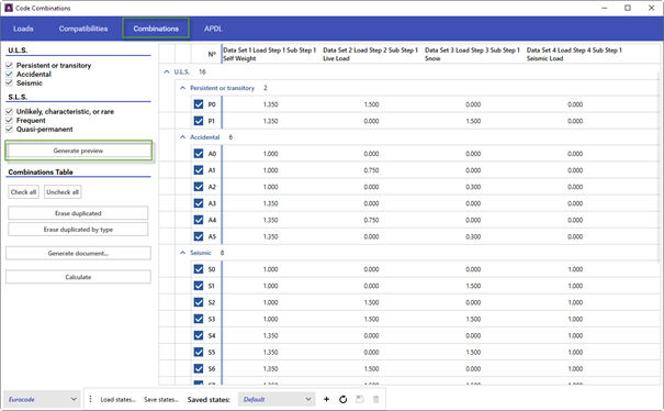
TARGET2 = Minimum X stress (SX-)”
TARGET5 = Maximum Y shear in absolute value. (FY*)”
...
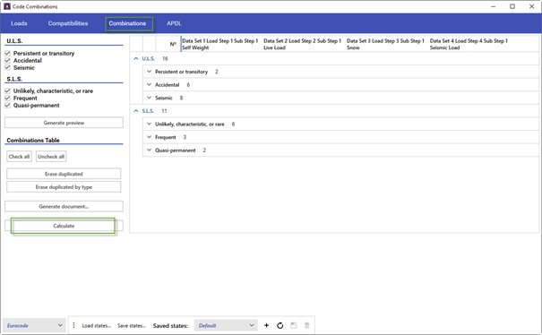
2. The combination rules are the conditions that control how the program combines the different Load Cases in order to achieve the extreme values or Targets. For example:
“Combination1 = Add two load cases chosen between [ (1.20 or 0.95) * LoadStep1, (0.95 or 0.00) * LoadStep2, (0.95 or 0.75) * LoadStep3]”
“Combination2 = (1.00 or -1.00) * Combination1”
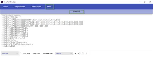
...
In the combination process, the program will follow the rules specified to produce target values at each point independently from the other points of the structure. Therefore, a result set will be achieved by combining the start states in a different way for each point.
All the basic results provided by ANSYS or the CivilFEM postprocessor are categorized into different data groups for their use in the combinations module. Within a chosen data group, targets and concomitance values will be calculated. These concomitance values will be the data in the group remaining values that does not pertain to the selected targets. For example, the BEAM data group includes forces, moments, stresses and strains in beam elements, that is: FX, FY, FZ, MX, MY, MZ, SDIR, SBYT, SBYB, SBZT, SBZB, EPELDIR, EPELBYT, EPELBYB, EPELBZT, EPELBZB. Therefore, if one of the Targets or desired result values is the maximum MZ (MZ+) bending moment, the program will obtain the maximum MZ moment and, simultaneously, the concomitant values FX, FY, FZ, MX, MY, SDIR, SBYT, SBYB, SBZT, SBZB, EPELDIR, EPELBYT, EPELBYB, EPELBZT, EPELBZB, of the same group.
A complete description of all the groups and their data can be found in Chapter 6.5.
A target is defined by the datum it refers to (for example MX) and by its TYPE (Minimum, Maximum or Maximum in absolute value) using the ~TRGDEF command.
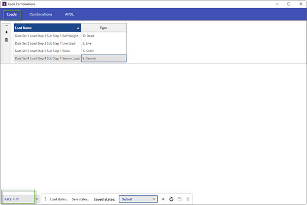
A combination rule is defined by its Start States and by the way in which the Start States are combined using the ~CMBDEF, ~STSTDEF and ~STSTCFT commands.
6.4 Types of Combination Rules
The types of COMBINATION rules that can be defined are:
Addition [ADD]
Addition with Variable Coefficients [ADDVC]
Incompatible or Exclusive Start States [INCOMPAT]
Compatible Start States [COMPATIB]
Optional Start States [OPTION]
Opposed Start States [OPOSED]
Selection of Start States [SELECT]
Selection of Start States with variable coefficients [SELECTVC]
6.4.1 Addition
Every Start State is added with fixed coefficients. Each Start State is only multiplied by one coefficient. This rule uses classic addition, equivalent to the combinations with ANSYS.
6.4.2 Addition with Variable Coefficients
Start States are added with variable coefficients. A maximum and minimum combination coefficient is assigned to each Start State. This rule can be used for combinations according to codes, for example, C = gfg · G + gfq · Q.
6.4.3 Incompatible or Exclusive Start States
Either a maximum Start State is selected from the defined states or no state is selected. It is not necessary to define coefficients. This rule is used as a representation of mobile loads that can only be placed in only one position at a given time.
6.4.4 Compatible Start States
Any Start State subset can be added together (all, many, one, or none of them). Coefficients are not necessary. This rule is used to represent live loads that can occur simultaneously (surface loads).
6.4.5 Optional Start States
Only one of the Start States is selected. Coefficients are not necessary. This rule is useful for selecting among different Start States. For example, different locations of a load on a pile, different code Start States, etc.
6.4.6 Opposed Start States
All the Start States of the combination are added, but each are multiplied by a maximum coefficient equal to +1 or a minimum coefficient equal to –1. This rule is useful for loads that act distinctly in two opposite directions (wind, earthquakes, etc.).
6.4.7 Selection of Start States
A fixed number of Start States, selected among the ones defined, is added. The number of Start States to be added is required input, not the coefficients. This rule is used for moveable loads that can act in more than one position.
6.4.8 Selection of Start States with Variable Coefficients
A fixed number of Start States are added and each one of them can be multiplied by two coefficients. Input requirements are the two coefficients per Start State and the number of Start States to be added. This is the most general type, but with degeneration it adapts to any of the previous types as shown in the table below.
|
TYPE |
Coefficient |
Number of Start States to add |
|
|
Maximum |
Minimum |
||
|
ADD |
C1* |
C2 = C1 |
ALL |
|
ADDVC |
C1* |
C2* |
ALL |
|
INCOMPAT |
0 |
1 |
1 |
|
COMPATIB |
0 |
1 |
ALL |
|
OPTION |
1 |
1 |
1 |
|
OPOSED |
1 |
-1 |
ALL |
|
SELECT |
1 |
1 |
NADD* |
|
SELECTVC |
C1* |
C2* |
NADD* |
* This data should be introduced by the user by means of ~CMBDEF and ~STSTCFT commands.
6.5 Data Groups
The determination of whether data a concomitant value or a target value is established at group level. A data group is the results set obtained by ANSYS or CivilFEM at a point of the model (node or vertex of an element for ANSYS or an element end for CivilFEM).
The elements implemented for each one of the groups are:
- Data relative to elements (obtained by ANSYS)
1. Beam elements group:
Link1, Beam3, Beam4, Link8, Link10, Pipe16, Pipe20, Beam23, Beam24, Beam44,
Beam54, Beam188, Beam189
2. Shell elements group:
Shell43, Shell63 and Shell93
3. Solid elements group:
Plane2, Plane25, Plane42, Solid45, Solid64, Solid65, Plane82, Plane83, Solid95,
Plane145, Plane146
4. Axial symmetric shells group:
Shell51, Shell61
- Data relative to nodes (obtained by ANSYS)
5. Displacements Group
6. Reactions Group
- Data relative to ends (obtained by CivilFEM)
7 Cross section Group
8 Shell vertices Group
The expected data groups and targets are the following:
6.5.1 Targets Group for Beam Elements Type
Includes forces, moments, stresses, strains, stress combination, strain combination at beam elements.
Table 6.5-1 Beam Elements Type
|
Item |
Component |
Type |
Label |
|
F |
X |
MIN |
FX- |
|
F |
Y |
MIN |
FY- |
|
F |
Z |
MIN |
FZ- |
|
M |
X |
MIN |
MX- |
|
M |
Y |
MIN |
MY- |
|
M |
Z |
MIN |
MZ- |
|
S |
DIR |
MIN |
SDIR- |
|
S |
BYT |
MIN |
SBYT- |
|
S |
BYB |
MIN |
SBYB- |
|
S |
BZT |
MIN |
SBZT- |
|
S |
BZB |
MIN |
SBZB- |
|
EPEL |
DIR |
MIN |
EPELDIR- |
|
EPEL |
BYT |
MIN |
EPELBYT- |
|
EPEL |
BYB |
MIN |
EPELBYB- |
|
EPEL |
BZT |
MIN |
EPELBZT- |
|
EPEL |
BZB |
MIN |
EPELBZB- |
|
COMBS |
YTZT |
MIN |
CMSYTZT- |
|
COMBS |
YTZM |
MIN |
CMSYTZM- |
|
COMBS |
YTZB |
MIN |
CMSYTZB- |
|
COMBS |
YMZT |
MIN |
CMSYMZT- |
|
COMBS |
YMZM |
MIN |
CMSYMZM- |
|
COMBS |
YMZB |
MIN |
CMSYMZB- |
|
COMBS |
YBZT |
MIN |
CMSYBZT- |
|
COMBS |
YBZM |
MIN |
CMSYBZM- |
|
COMBS |
YBZB |
MIN |
CMSYBZB- |
|
COMBEPEL |
YTZT |
MIN |
CMEYTZT- |
|
COMBEPEL |
YTZM |
MIN |
CMEYTZM- |
|
COMBEPEL |
YTZB |
MIN |
CMEYTZB- |
|
COMBEPEL |
YMZT |
MIN |
CMEYMZT- |
|
COMBEPEL |
YMZM |
MIN |
CMEYMZM- |
|
COMBEPEL |
YMZB |
MIN |
CMEYMZB- |
|
COMBEPEL |
YBZT |
MIN |
CMEYBZT- |
|
COMBEPEL |
YBZM |
MIN |
CMEYBZM- |
|
COMBEPEL |
YBZB |
MIN |
CMEYBZB- |
|
F |
X |
MAX |
FX+ |
|
F |
Y |
MAX |
FY+ |
|
F |
Z |
MAX |
FZ+ |
|
M |
X |
MAX |
MX+ |
|
M |
Y |
MAX |
MY+ |
|
M |
Z |
MAX |
MZ+ |
|
S |
DIR |
MAX |
SDIR+ |
|
S |
BYT |
MAX |
SBYT+ |
|
S |
BYB |
MAX |
SBYB+ |
|
S |
BZT |
MAX |
SBZT+ |
|
S |
BZB |
MAX |
SBZB+ |
|
EPEL |
DIR |
MAX |
EPELDIR+ |
|
EPEL |
BYT |
MAX |
EPELBYT+ |
|
EPEL |
BYB |
MAX |
EPELBYB+ |
|
EPEL |
BZT |
MAX |
EPELBZT+ |
|
EPEL |
BZB |
MAX |
EPELBZB+ |
|
COMBS |
YTZT |
MAX |
CMSYTZT+ |
|
COMBS |
YTZM |
MAX |
CMSYTZM+ |
|
COMBS |
YTZB |
MAX |
CMSYTZB+ |
|
COMBS |
YMZT |
MAX |
CMSYMZT+ |
|
COMBS |
YMZM |
MAX |
CMSYMZM+ |
|
COMBS |
YMZB |
MAX |
CMSYMZB+ |
|
COMBS |
YBZT |
MAX |
CMSYBZT+ |
|
COMBS |
YBZM |
MAX |
CMSYBZM+ |
|
COMBS |
YBZB |
MAX |
CMSYBZB+ |
|
COMBEPEL |
YTZT |
MAX |
CMEYTZT+ |
|
COMBEPEL |
YTZM |
MAX |
CMEYTZM+ |
|
COMBEPEL |
YTZB |
MAX |
CMEYTZB+ |
|
COMBEPEL |
YMZT |
MAX |
CMEYMZT+ |
|
COMBEPEL |
YMZM |
MAX |
CMEYMZM+ |
|
COMBEPEL |
YMZB |
MAX |
CMEYMZB+ |
|
COMBEPEL |
YBZT |
MAX |
CMEYBZT+ |
|
COMBEPEL |
YBZM |
MAX |
CMEYBZM+ |
|
COMBEPEL |
YBZB |
MAX |
CMEYBZB+ |
|
F |
X |
ABS |
FX* |
|
F |
Y |
ABS |
FY* |
|
F |
Z |
ABS |
FZ* |
|
M |
X |
ABS |
MX* |
|
M |
Y |
ABS |
MY* |
|
M |
Z |
ABS |
MZ* |
|
S |
DIR |
ABS |
SDIR* |
|
S |
BYT |
ABS |
SBYT* |
|
S |
BYB |
ABS |
SBYB* |
|
S |
BZT |
ABS |
SBZT* |
|
S |
BZB |
ABS |
SBZB* |
|
EPEL |
DIR |
ABS |
EPELDIR* |
|
EPEL |
BYT |
ABS |
EPELBYT* |
|
EPEL |
BYB |
ABS |
EPELBYB* |
|
EPEL |
BZT |
ABS |
EPELBZT* |
|
EPEL |
BZB |
ABS |
EPELBZB* |
|
COMBS |
YTZT |
ABS |
CMSYTZT* |
|
COMBS |
YTZM |
ABS |
CMSYTZM* |
|
COMBS |
YTZB |
ABS |
CMSYTZB* |
|
COMBS |
YMZT |
ABS |
CMSYMZT* |
|
COMBS |
YMZM |
ABS |
CMSYMZM* |
|
COMBS |
YMZB |
ABS |
CMSYMZB* |
|
COMBS |
YBZT |
ABS |
CMSYBZT* |
|
COMBS |
YBZM |
ABS |
CMSYBZM* |
|
COMBS |
YBZB |
ABS |
CMSYBZB* |
|
COMBEPEL |
YTZT |
ABS |
CMEYTZT* |
|
COMBEPEL |
YTZM |
ABS |
CMEYTZM* |
|
COMBEPEL |
YTZB |
ABS |
CMEYTZB* |
|
COMBEPEL |
YMZT |
ABS |
CMEYMZT* |
|
COMBEPEL |
YMZM |
ABS |
CMEYMZM* |
|
COMBEPEL |
YMZB |
ABS |
CMEYMZB* |
|
COMBEPEL |
YBZT |
ABS |
CMEYBZT* |
|
COMBEPEL |
YBZM |
ABS |
CMEYBZM* |
|
COMBEPEL |
YBZB |
ABS |
CMEYBZB* |
6.5.2 Targets Group for Shell Elements Type
Includes forces, moments, stresses and strains for a shell element type.
Table 6.5-2 Shell Elements Type
|
Item |
Component |
Type |
Label |
|
T |
X |
MIN |
TX- |
|
T |
Y |
MIN |
TY- |
|
T |
XY |
MIN |
TXY- |
|
M |
X |
MIN |
MX- |
|
M |
Y |
MIN |
MY- |
|
M |
XY |
MIN |
MXY- |
|
N |
X |
MIN |
NX- |
|
N |
Y |
MIN |
NY- |
|
S |
XT |
MIN |
SXT- |
|
S |
YT |
MIN |
SYT- |
|
S |
ZT |
MIN |
SZT- |
|
S |
XYT |
MIN |
SXYT- |
|
S |
YZT |
MIN |
SYZT- |
|
S |
XZT |
MIN |
SXZT- |
|
S |
XB |
MIN |
SXB- |
|
S |
YB |
MIN |
SYB- |
|
S |
ZB |
MIN |
SZB- |
|
S |
XYB |
MIN |
SXYB- |
|
S |
YZB |
MIN |
SYZB- |
|
S |
XZB |
MIN |
SXZB- |
|
EPEL |
XT |
MIN |
EPELXT- |
|
EPEL |
YT |
MIN |
EPELYT- |
|
EPEL |
ZT |
MIN |
EPELZT- |
|
EPEL |
XYT |
MIN |
EPELXYT- |
|
EPEL |
YZT |
MIN |
EPELYZT- |
|
EPEL |
XZT |
MIN |
EPELXZT- |
|
EPEL |
XB |
MIN |
EPELXB- |
|
EPEL |
YB |
MIN |
EPELYB- |
|
EPEL |
ZB |
MIN |
EPELZB- |
|
EPEL |
XYB |
MIN |
EPELXYB- |
|
EPEL |
YZB |
MIN |
EPELYZB- |
|
EPEL |
XZB |
MIN |
EPELXZB- |
|
T |
X |
MAX |
TX+ |
|
T |
Y |
MAX |
TY+ |
|
T |
XY |
MAX |
TXY+ |
|
M |
X |
MAX |
MX+ |
|
M |
Y |
MAX |
MY+ |
|
M |
XY |
MAX |
MXY+ |
|
N |
X |
MAX |
NX+ |
|
N |
Y |
MAX |
NY+ |
|
S |
XT |
MAX |
SXT+ |
|
S |
YT |
MAX |
SYT+ |
|
S |
ZT |
MAX |
SZT+ |
|
S |
XYT |
MAX |
SXYT+ |
|
S |
YZT |
MAX |
SYZT+ |
|
S |
XZT |
MAX |
SXZT+ |
|
S |
XB |
MAX |
SXB+ |
|
S |
YB |
MAX |
SYB+ |
|
S |
ZB |
MAX |
SZB+ |
|
S |
XYB |
MAX |
SXYB+ |
|
S |
YZB |
MAX |
SYZB+ |
|
S |
XZB |
MAX |
SXZB+ |
|
EPEL |
XT |
MAX |
EPELXT+ |
|
EPEL |
YT |
MAX |
EPELYT+ |
|
EPEL |
ZT |
MAX |
EPELZT+ |
|
EPEL |
XYT |
MAX |
EPELXYT+ |
|
EPEL |
YZT |
MAX |
EPELYZT+ |
|
EPEL |
XZT |
MAX |
EPELXZT+ |
|
EPEL |
XB |
MAX |
EPELXB+ |
|
EPEL |
YB |
MAX |
EPELYB+ |
|
EPEL |
ZB |
MAX |
EPELZB+ |
|
EPEL |
XYB |
MAX |
EPELXYB+ |
|
EPEL |
YZB |
MAX |
EPELYZB+ |
|
EPEL |
XZB |
MAX |
EPELXZB+ |
|
T |
X |
ABS |
TX* |
|
T |
Y |
ABS |
TY* |
|
T |
XY |
ABS |
TXY* |
|
M |
X |
ABS |
MX* |
|
M |
Y |
ABS |
MY* |
|
M |
XY |
ABS |
MXY* |
|
N |
X |
ABS |
NX* |
|
N |
Y |
ABS |
NY* |
|
S |
XT |
ABS |
SXT* |
|
S |
YT |
ABS |
SYT* |
|
S |
ZT |
ABS |
SZT* |
|
S |
XYT |
ABS |
SXYT* |
|
S |
YZT |
ABS |
SYZT* |
|
S |
XZT |
ABS |
SXZT* |
|
S |
XB |
ABS |
SXB* |
|
S |
YB |
ABS |
SYB* |
|
S |
ZB |
ABS |
SZB* |
|
S |
XYB |
ABS |
SXYB* |
|
S |
YZB |
ABS |
SYZB* |
|
S |
XZB |
ABS |
SXZB* |
|
EPEL |
XT |
ABS |
EPELXT* |
|
EPEL |
YT |
ABS |
EPELYT* |
|
EPEL |
ZT |
ABS |
EPELZT* |
|
EPEL |
XYT |
ABS |
EPELXYT* |
|
EPEL |
YZT |
ABS |
EPELYZT* |
|
EPEL |
XZT |
ABS |
EPELXZT* |
|
EPEL |
XB |
ABS |
EPELXB* |
|
EPEL |
YB |
ABS |
EPELYB* |
|
EPEL |
ZB |
ABS |
EPELZB* |
|
EPEL |
XYB |
ABS |
EPELXYB* |
|
EPEL |
YZB |
ABS |
EPELYZB* |
|
EPEL |
XZB |
ABS |
EPELXZB* |
6.5.3 Targets Group for Solid Elements Type
Includes 2D or 3D forces, stresses and strains for a solid elements type.
Table 6.5-3 Solid Elements Type
|
Item |
Component |
Type |
Label |
|
S |
X |
MIN |
SX- |
|
S |
Y |
MIN |
SY- |
|
S |
Z |
MIN |
SZ- |
|
S |
XY |
MIN |
SXY- |
|
S |
YZ |
MIN |
SYZ- |
|
S |
XZ |
MIN |
SXZ- |
|
EPEL |
X |
MIN |
EPELX- |
|
EPEL |
Y |
MIN |
EPELY- |
|
EPEL |
Z |
MIN |
EPELZ- |
|
EPEL |
XY |
MIN |
EPELXY- |
|
EPEL |
YZ |
MIN |
EPELYZ- |
|
EPEL |
XZ |
MIN |
EPELXZ- |
|
S |
X |
MAX |
SX+ |
|
S |
Y |
MAX |
SY+ |
|
S |
Z |
MAX |
SZ+ |
|
S |
XY |
MAX |
SXY+ |
|
S |
YZ |
MAX |
SYZ+ |
|
S |
XZ |
MAX |
SXZ+ |
|
EPEL |
X |
MAX |
EPELX+ |
|
EPEL |
Y |
MAX |
EPELY+ |
|
EPEL |
Z |
MAX |
EPELZ+ |
|
EPEL |
XY |
MAX |
EPELXY+ |
|
EPEL |
YZ |
MAX |
EPELYZ+ |
|
EPEL |
XZ |
MAX |
EPELXZ+ |
|
S |
X |
ABS |
SX* |
|
S |
Y |
ABS |
SY* |
|
S |
Z |
ABS |
SZ* |
|
S |
XY |
ABS |
SXY* |
|
S |
YZ |
ABS |
SYZ* |
|
S |
XZ |
ABS |
SXZ* |
|
EPEL |
X |
ABS |
EPELX* |
|
EPEL |
Y |
ABS |
EPELY* |
|
EPEL |
Z |
ABS |
EPELZ* |
|
EPEL |
XY |
ABS |
EPELXY* |
|
EPEL |
YZ |
ABS |
EPELYZ* |
|
EPEL |
XZ |
ABS |
EPELXZ* |
6.5.4 Targets Group for Axial Symmetric Shell Elements Type
Includes forces, moments, stresses and strains at axial symmetric shell elements.
Table 6.5-4 Axis Symmetric Shell Elements Type
|
Item |
Component |
Type |
Label |
|
F |
X |
MIN |
FX- |
|
F |
Y |
MIN |
FY- |
|
F |
Z |
MIN |
FZ- |
|
M |
Z |
MIN |
MZ- |
|
S |
MT |
MIN |
SMT- |
|
S |
THKT |
MIN |
STHKT- |
|
S |
HT |
MIN |
SHT- |
|
S |
MHT |
MIN |
SMHT- |
|
S |
MM |
MIN |
SMM- |
|
S |
THKM |
MIN |
STHKM- |
|
S |
HM |
MIN |
SHM- |
|
S |
MHM |
MIN |
SMHM- |
|
S |
MB |
MIN |
SMB- |
|
S |
THKB |
MIN |
STHKB- |
|
S |
HB |
MIN |
SHB- |
|
S |
MHB |
MIN |
SMHB- |
|
EPEL |
MT |
MIN |
EPELMT- |
|
EPEL |
THKT |
MIN |
EPELTHKT- |
|
EPEL |
HT |
MIN |
EPELHT- |
|
EPEL |
MHT |
MIN |
EPELMHT- |
|
EPEL |
MM |
MIN |
EPELMM- |
|
EPEL |
THKM |
MIN |
EPELTHKM- |
|
EPEL |
HM |
MIN |
EPELHM- |
|
EPEL |
MHM |
MIN |
EPELMHM- |
|
EPEL |
MB |
MIN |
EPELMB- |
|
EPEL |
THKB |
MIN |
EPELTHKB- |
|
EPEL |
HB |
MIN |
EPELHB- |
|
EPEL |
MHB |
MIN |
EPELMHB- |
|
F |
X |
MAX |
FX+ |
|
F |
Y |
MAX |
FY+ |
|
F |
Z |
MAX |
FZ+ |
|
M |
Z |
MAX |
MZ+ |
|
S |
MT |
MAX |
SMT+ |
|
S |
THKT |
MAX |
STHKT+ |
|
S |
HT |
MAX |
SHT+ |
|
S |
MHT |
MAX |
SMHT+ |
|
S |
MM |
MAX |
SMM+ |
|
S |
THKM |
MAX |
STHKM+ |
|
S |
HM |
MAX |
SHM+ |
|
S |
MHM |
MAX |
SMHM+ |
|
S |
MB |
MAX |
SMB+ |
|
S |
THKB |
MAX |
STHKB+ |
|
S |
HB |
MAX |
SHB+ |
|
S |
MHB |
MAX |
SMHB+ |
|
EPEL |
MT |
MAX |
EPELMT+ |
|
EPEL |
THKT |
MAX |
EPELTHKT+ |
|
EPEL |
HT |
MAX |
EPELHT+ |
|
EPEL |
MHT |
MAX |
EPELMHT+ |
|
EPEL |
MM |
MAX |
EPELMM+ |
|
EPEL |
THKM |
MAX |
EPELTHKM+ |
|
EPEL |
HM |
MAX |
EPELHM+ |
|
EPEL |
MHM |
MAX |
EPELMHM+ |
|
EPEL |
MB |
MAX |
EPELMB+ |
|
EPEL |
THKB |
MAX |
EPELTHKB+ |
|
EPEL |
HB |
MAX |
EPELHB+ |
|
EPEL |
MHB |
MAX |
EPELMHB+ |
|
|
|
|
|
|
F |
X |
ABS |
FX* |
|
F |
Y |
ABS |
FY* |
|
F |
Z |
ABS |
FZ* |
|
M |
Z |
ABS |
MZ* |
|
S |
MT |
ABS |
SMT* |
|
S |
THKT |
ABS |
STHKT* |
|
S |
HT |
ABS |
SHT* |
|
S |
MHT |
ABS |
SMHT* |
|
S |
MM |
ABS |
SMM* |
|
S |
THKM |
ABS |
STHKM* |
|
S |
HM |
ABS |
SHM* |
|
S |
MHM |
ABS |
SMHM* |
|
S |
MB |
ABS |
SMB* |
|
S |
THKB |
ABS |
STHKB* |
|
S |
HB |
ABS |
SHB* |
|
S |
MHB |
ABS |
SMHB* |
|
EPEL |
MT |
ABS |
EPELMT* |
|
EPEL |
THKT |
ABS |
EPELTHKT* |
|
EPEL |
HT |
ABS |
EPELHT* |
|
EPEL |
MHT |
ABS |
EPELMHT* |
|
EPEL |
MM |
ABS |
EPELMM* |
|
EPEL |
THKM |
ABS |
EPELTHKM* |
|
EPEL |
HM |
ABS |
EPELHM* |
|
EPEL |
MHM |
ABS |
EPELMHM* |
|
EPEL |
MB |
ABS |
EPELMB* |
|
EPEL |
THKB |
ABS |
EPELTHKB* |
|
EPEL |
HB |
ABS |
EPELHB* |
|
EPEL |
MHB |
ABS |
EPELMHB* |
6.5.5 Targets Group for Displacements
Includes displacements and rotations at the nodes.
Table 6.5-5 Displacements
|
Item |
Component |
Type |
Label |
|
U |
X |
MIN |
UX- |
|
U |
Y |
MIN |
UY- |
|
U |
Z |
MIN |
UZ- |
|
ROT |
X |
MIN |
ROTX- |
|
ROT |
Y |
MIN |
ROTY- |
|
ROT |
Z |
MIN |
ROTZ- |
|
U |
X |
MAX |
UX+ |
|
U |
Y |
MAX |
UY+ |
|
U |
Z |
MAX |
UZ+ |
|
ROT |
X |
MAX |
ROTX+ |
|
ROT |
Y |
MAX |
ROTY+ |
|
ROT |
Z |
MAX |
ROTZ+ |
|
U |
X |
ABS |
UX* |
|
U |
Y |
ABS |
UY* |
|
U |
Z |
ABS |
UZ* |
|
ROT |
X |
ABS |
ROTX* |
|
ROT |
Y |
ABS |
ROTY* |
|
ROT |
Z |
ABS |
ROTZ* |
6.5.6 Targets Group for Nodal Reactions
Includes forces and moments as reactions at the nodes.
Table 6.5-5 Reactions
|
Item |
Component |
Type |
Label |
|
F |
X |
MIN |
FX- |
|
F |
Y |
MIN |
FY- |
|
F |
Z |
MIN |
FZ- |
|
M |
X |
MIN |
MX- |
|
M |
Y |
MIN |
MY- |
|
M |
Z |
MIN |
MZ- |
|
F |
X |
MAX |
FX+ |
|
F |
Y |
MAX |
FY+ |
|
F |
Z |
MAX |
FZ+ |
|
M |
X |
MAX |
MX+ |
|
M |
Y |
MAX |
MY+ |
|
M |
Z |
MAX |
MZ+ |
|
F |
X |
ABS |
FX* |
|
F |
Y |
ABS |
FY* |
|
F |
Z |
ABS |
FZ* |
|
M |
X |
ABS |
MX* |
|
M |
Y |
ABS |
MY* |
|
M |
Z |
ABS |
MZ* |
6.5.7 Targets Group for Cross Sections
This group includes forces, moments, stresses, and strains at the points of the section calculated by CivilFEM and is filed in the CivilFEM results file (.RCV).
Given that the number of points in a section is variable and may grow indefinitely, the number of targets is limited to 6 for forces and moments, 14 for stresses and 14 for strains. For the last two cases, the target refers to a point and a component of the stress or strain at that point, defined by the user (see ~TRGUPT command).
However, concomitance is established for all data composed of the forces and moments of the section and all the components of the stresses and strains at every point of the section.
The user can define a set of stress or strain points, represented in the following table by PT1, PT2 … PTn.
Table 6.5-7 Cross Sections
|
Item |
Component |
Type |
Label |
|
F |
X |
MIN |
FX- |
|
F |
Y |
MIN |
FY- |
|
F |
Z |
MIN |
FZ- |
|
M |
X |
MIN |
MX- |
|
M |
Y |
MIN |
MY- |
|
M |
Z |
MIN |
MZ- |
|
SS |
PT1 |
MIN |
SSPT1- |
|
SS |
PT2 |
MIN |
SSPT2- |
|
SS |
PT3 |
MIN |
SSPT3- |
|
SS |
PT4 |
MIN |
SSPT4- |
|
SS |
PT5 |
MIN |
SSPT5- |
|
SS |
PT6 |
MIN |
SSPT6- |
|
SS |
PT7 |
MIN |
SSPT7- |
|
SS |
PT8 |
MIN |
SSPT8- |
|
SS |
PT9 |
MIN |
SSPT9- |
|
SS |
PT10 |
MIN |
SSPT10- |
|
SS |
PT11 |
MIN |
SSPT11- |
|
SS |
PT12 |
MIN |
SSPT12- |
|
SS |
PT13 |
MIN |
SSPT13- |
|
SS |
PT14 |
MIN |
SSPT14- |
|
EP |
PT1 |
MIN |
EPPT1- |
|
EP |
PT2 |
MIN |
EPPT2- |
|
EP |
PT3 |
MIN |
EPPT3- |
|
EP |
PT4 |
MIN |
EPPT4- |
|
EP |
PT5 |
MIN |
EPPT5- |
|
EP |
PT6 |
MIN |
EPPT6- |
|
EP |
PT7 |
MIN |
EPPT7- |
|
EP |
PT8 |
MIN |
EPPT8- |
|
EP |
PT9 |
MIN |
EPPT9- |
|
EP |
PT10 |
MIN |
EPPT10- |
|
EP |
PT11 |
MIN |
EPPT11- |
|
EP |
PT12 |
MIN |
EPPT12- |
|
EP |
PT13 |
MIN |
EPPT13- |
|
EP |
PT14 |
MIN |
EPPT14- |
|
F |
X |
MAX |
FX+ |
|
F |
Y |
MAX |
FY+ |
|
F |
Z |
MAX |
FZ+ |
|
M |
X |
MAX |
MX+ |
|
M |
Y |
MAX |
MY+ |
|
M |
Z |
MAX |
MZ+ |
|
SS |
PT1 |
MAX |
SSPT1+ |
|
SS |
PT2 |
MAX |
SSPT2+ |
|
SS |
PT3 |
MAX |
SSPT3+ |
|
SS |
PT4 |
MAX |
SSPT4+ |
|
SS |
PT5 |
MAX |
SSPT5+ |
|
SS |
PT6 |
MAX |
SSPT6+ |
|
SS |
PT7 |
MAX |
SSPT7+ |
|
SS |
PT8 |
MAX |
SSPT8+ |
|
SS |
PT9 |
MAX |
SSPT9+ |
|
SS |
PT10 |
MAX |
SSPT10+ |
|
SS |
PT11 |
MAX |
SSPT11+ |
|
SS |
PT12 |
MAX |
SSP12+ |
|
SS |
PT13 |
MAX |
SSPT13+ |
|
SS |
PT14 |
MAX |
SSPT14+ |
|
EP |
PT1 |
MAX |
EPT1+ |
|
EP |
PT2 |
MAX |
EPT2+ |
|
EP |
PT3 |
MAX |
EPT3+ |
|
EP |
PT4 |
MAX |
EPT4+ |
|
EP |
PT5 |
MAX |
EPPT5+ |
|
EP |
PT6 |
MAX |
EPPT6+ |
|
EP |
PT7 |
MAX |
EPPT7+ |
|
EP |
PT8 |
MAX |
EPPT8+ |
|
EP |
PT9 |
MAX |
EPPT9+ |
|
EP |
PT10 |
MAX |
EPPT10+ |
|
EP |
PT11 |
MAX |
EPPT11+ |
|
EP |
PT12 |
MAX |
EPPT12+ |
|
EP |
PT13 |
MAX |
EPPT13+ |
|
EP |
PT14 |
MAX |
EPPT14+ |
|
F |
X |
ABS |
FX* |
|
F |
Y |
ABS |
FY* |
|
F |
Z |
ABS |
FZ* |
|
M |
X |
ABS |
MX* |
|
M |
Y |
ABS |
MY* |
|
M |
Z |
ABS |
MZ* |
|
SS |
PT1 |
ABS |
SSPT1* |
|
SS |
PT2 |
ABS |
SSPT2* |
|
SS |
PT3 |
ABS |
SSPT3* |
|
SS |
PT4 |
ABS |
SSPT4* |
|
SS |
PT5 |
ABS |
SSPT5* |
|
SS |
PT6 |
ABS |
SSPT6* |
|
SS |
PT7 |
ABS |
SSPT7* |
|
SS |
PT8 |
ABS |
SSPT8* |
|
SS |
PT9 |
ABS |
SSPT9* |
|
SS |
PT10 |
ABS |
SSPT10* |
|
SS |
PT11 |
ABS |
SSPT11* |
|
SS |
PT12 |
ABS |
SSP12* |
|
SS |
PT13 |
ABS |
SSPT13* |
|
SS |
PT14 |
ABS |
SSPT14* |
|
EP |
PT1 |
ABS |
EPT1* |
|
EP |
PT2 |
ABS |
EPT2* |
|
EP |
PT3 |
ABS |
EPT3* |
|
EP |
PT4 |
ABS |
EPT4* |
|
EP |
PT5 |
ABS |
EPPT5* |
|
EP |
PT6 |
ABS |
EPPT6* |
|
EP |
PT7 |
ABS |
EPPT7* |
|
EP |
PT8 |
ABS |
EPPT8* |
|
EP |
PT9 |
ABS |
EPPT9* |
|
EP |
PT10 |
ABS |
EPPT10* |
|
EP |
PT11 |
ABS |
EPPT11* |
|
EP |
PT12 |
ABS |
EPPT12* |
|
EP |
PT13 |
ABS |
EPPT13* |
|
EP |
PT14 |
ABS |
EPPT14* |
6.5.8 Targets Group for Shell Vertices
They include forces, moments, stresses and strains obtained by CivilFEM in the shell vertices and stored in the CivilFEM results file (.RCV).
Table 6.5-8 Shell elements
|
Item |
Component |
Type |
Label |
|
T |
X |
MIN |
TX- |
|
T |
Y |
MIN |
TY- |
|
T |
XY |
MIN |
TXY- |
|
M |
X |
MIN |
MX- |
|
M |
Y |
MIN |
MY- |
|
M |
XY |
MIN |
MXY- |
|
N |
X |
MIN |
NX- |
|
N |
Y |
MIN |
NY- |
|
S |
XT |
MIN |
SXT- |
|
S |
YT |
MIN |
SYT- |
|
S |
ZT |
MIN |
SZT- |
|
S |
XYT |
MIN |
SXYT- |
|
S |
YZT |
MIN |
SYZT- |
|
S |
XZT |
MIN |
SXZT- |
|
S |
XB |
MIN |
SXB- |
|
S |
YB |
MIN |
SYB- |
|
S |
ZB |
MIN |
SZB- |
|
S |
XYB |
MIN |
SXYB- |
|
S |
YZB |
MIN |
SYZB- |
|
S |
XZB |
MIN |
SXZB- |
|
EPEL |
XT |
MIN |
EPELXT- |
|
EPEL |
YT |
MIN |
EPELYT- |
|
EPEL |
ZT |
MIN |
EPELZT- |
|
EPEL |
XYT |
MIN |
EPELXYT- |
|
EPEL |
YZT |
MIN |
EPELYZT- |
|
EPEL |
XZT |
MIN |
EPELXZT- |
|
EPEL |
XB |
MIN |
EPELXB- |
|
EPEL |
YB |
MIN |
EPELYB- |
|
EPEL |
ZB |
MIN |
EPELZB- |
|
EPEL |
XYB |
MIN |
EPELXYB- |
|
EPEL |
YZB |
MIN |
EPELYZB- |
|
EPEL |
XZB |
MIN |
EPELXZB- |
|
T |
X |
MAX |
TX+ |
|
T |
Y |
MAX |
TY+ |
|
T |
XY |
MAX |
TXY+ |
|
M |
X |
MAX |
MX+ |
|
M |
Y |
MAX |
MY+ |
|
M |
XY |
MAX |
MXY+ |
|
N |
X |
MAX |
NX+ |
|
N |
Y |
MAX |
NY+ |
|
S |
XT |
MAX |
SXT+ |
|
S |
YT |
MAX |
SYT+ |
|
S |
ZT |
MAX |
SZT+ |
|
S |
XYT |
MAX |
SXYT+ |
|
S |
YZT |
MAX |
SYZT+ |
|
S |
XZT |
MAX |
SXZT+ |
|
S |
XB |
MAX |
SXB+ |
|
S |
YB |
MAX |
SYB+ |
|
S |
ZB |
MAX |
SZB+ |
|
S |
XYB |
MAX |
SXYB+ |
|
S |
YZB |
MAX |
SYZB+ |
|
S |
XZB |
MAX |
SXZB+ |
|
EPEL |
XT |
MAX |
EPELXT+ |
|
EPEL |
YT |
MAX |
EPELYT+ |
|
EPEL |
ZT |
MAX |
EPELZT+ |
|
EPEL |
XYT |
MAX |
EPELXYT+ |
|
EPEL |
YZT |
MAX |
EPELYZT+ |
|
EPEL |
XZT |
MAX |
EPELXZT+ |
|
EPEL |
XB |
MAX |
EPELXB+ |
|
EPEL |
YB |
MAX |
EPELYB+ |
|
EPEL |
ZB |
MAX |
EPELZB+ |
|
EPEL |
XYB |
MAX |
EPELXYB+ |
|
EPEL |
YZB |
MAX |
EPELYZB+ |
|
EPEL |
XZB |
MAX |
EPELXZB+ |
|
T |
X |
ABS |
TX* |
|
T |
Y |
ABS |
TY* |
|
T |
XY |
ABS |
TXY* |
|
M |
X |
ABS |
MX* |
|
M |
Y |
ABS |
MY* |
|
M |
XY |
ABS |
MXY* |
|
N |
X |
ABS |
NX* |
|
N |
Y |
ABS |
NY* |
|
S |
XT |
ABS |
SXT* |
|
S |
YT |
ABS |
SYT* |
|
S |
ZT |
ABS |
SZT* |
|
S |
XYT |
ABS |
SXYT* |
|
S |
YZT |
ABS |
SYZT* |
|
S |
XZT |
ABS |
SXZT* |
|
S |
XB |
ABS |
SXB* |
|
S |
YB |
ABS |
SYB* |
|
S |
ZB |
ABS |
SZB* |
|
S |
XYB |
ABS |
SXYB* |
|
S |
YZB |
ABS |
SYZB* |
|
S |
XZB |
ABS |
SXZB* |
|
EPEL |
XT |
ABS |
EPELXT* |
|
EPEL |
YT |
ABS |
EPELYT* |
|
EPEL |
ZT |
ABS |
EPELZT* |
|
EPEL |
XYT |
ABS |
EPELXYT* |
|
EPEL |
YZT |
ABS |
EPELYZT* |
|
EPEL |
XZT |
ABS |
EPELXZT* |
|
EPEL |
XB |
ABS |
EPELXB* |
|
EPEL |
YB |
ABS |
EPELYB* |
|
EPEL |
ZB |
ABS |
EPELZB* |
|
EPEL |
XYB |
ABS |
EPELXYB* |
|
EPEL |
YZB |
ABS |
EPELYZB* |
|
EPEL |
XZB |
ABS |
EPELXZB* |
6.6 Envelopes
The data stored in the CivilFEM results file are stored in two different types of data blocks: blocks of stresses, forces, moments and strains and blocks of alternatives.
Data blocks of stresses, forces, moments and strains are associated to an ANSYS DataSet and are obtained and stored in solution time. The content of these blocks is similar and their structure is always the same.
Alternative blocks differ from each other in their content because their content varies depending on the process (checking, design, etc.) that generated the alternative. The data are obtained in postprocessor time, storing the data of forces, moments, stresses and strains from the corresponding blocks. Each block of forces, moments, stresses and strains may generate one or more alternative blocks (checking according to different codes or changing various parameters).
The utilities of the combination module are ONLY applied to the blocks of stresses, forces, moments and strains associated to an ANSYS DataSet.
The utility ENVELOPE has been developed for alternative blocks. This utility is included in the generation and usage of the file *.RCV which allows the creation of other alternatives as envelope of others previously obtained. Envelopes have to be homogeneous; specifically, they must be obtained by the application of the same code and process to the same model. The resulting alternative will be homogeneous with the previous ones, with a similar identification and the same commands for reading, drawing and representation.
There are 3 types of envelopes:
· Maximum values envelope
· Minimum values envelope
· Maximum absolute value envelope.
An envelope of several alternatives consists of initial envelopes; these envelopes contain the set of minimum, maximum or absolute maximum values (depending on type) of data taken from all of the initial alternatives.
6.7 Concomitance at Load and Model Level
The coefficients that are used to multiply the Start States of a combination that achieve a certain Target at a specific node of the structure can be obtained with the ~CMBINQ command. This command displays a list of the coefficients utilized in each one of the Start States of the combination rule. It is also possible for this command to display the coefficients of Start States in a nested combination.
With this command, the TARGET combined result as well as any concomitant values of the TARGET group can be determined.
It will allow the user to define the load state that will determine the requested Target by calculating the coefficients of each start state of the specified combination rule. Likewise, every start state coefficient from all the combinations will be calculated in the same way.
For the specific combination rule selected, the concomitant loads in the model are stored in the ANSYS and CivilFEM databases. The results for this load step will be available until a new Data Set is specified by means of the ~CFSET or ~CMBDAT commands. The results from the ~CMBINQ command cannot be used for checking or dimensioning operations conforming to codes.
6.8 Comments about Beam188 and Beam189 Elements
The ANSYS commands PLDISP or PLNSOL, U plot the deformed shape of a beam structure, beginning with the nodal displacements for all types of beam elements; the plot will display the linear structure with its deformed shape.
If the option /ESHAPE,1 is activated (plot the section shape), ANSYS converts the linear elements into a rectangular section, taking its characteristics from the real constants. This section remains undeformed throughout the element; except, with BEAM188 and BEAM189 elements, ANSYS contains additional information such as the section shape, cross section cells (subdivision) and output information at the section nodes. Due to this additional information, ANSYS can calculate and plot the element’s deformed shape as well as the deformed shape at the section’s internal nodes for these two element types.
ANSYS stores the information about nodal displacements and section strains in the results file (file.RST).
When combinations are performed in CivilFEM, a results file (file.CMB) is generated with the same format as the ANSYS results file (file.RST); ANSYS can read this CMB file as if it were an RST file, taking all the required postprocessing information from this file, such as the deformed shape of the structure.
As in CivilFEM, after performing the combinations, ANSYS establishes the concomitance at the group level (as discussed previously); when performing a combination for a target of displacements, concomitant data will be the remaining displacements and rotations, but not the section strains which will be left as zero.
For this reason, if the commands PLDISP and PLNSOL,U are applied with the option /ESHAPE,1 on a structure with Beam188 and Beam189 elements, the program will not plot the deformed shape correctly for a combined result of a displacement target. Nevertheless it is still possible to list the correct results.
To plot the correct results, it is necessary to use the option /ESHAPE,0.
6.9 Start State Combinations with Prestressing Tendons
If the start states used within combinations contain results from a prestressed concrete structure, consult the corresponding chapter of the Advanced Prestressed Concrete Module documentation for further considerations.
6.10 Calculation of All Possible Load Cases
In some cases it may be useful to obtain all the load cases that a certain combination rule can generate. The process is as follows:
- Define combination rules. As seen in Chapter 6.4.
- Perform combinations by using the ~LINCMB command.
- Review results.
The load cases are obtained by linearly by combining the initial load steps, as defined in the combination rules, with the desired coefficients.
These new load cases are stored in the RCV and RST files (no CMB or CVMB files are created), after the initial load cases. To postprocess these load cases, it is necessary to read them first, just as any other load case (~CFSET command).
A list of all the newly generated load cases can be obtained with the ~LINLST command. This list will provide information about the combination rule of each load case, the initial load cases and the coefficients used (only available if the RCV file has been created).
Note:
It is important to keep in mind that Load Combinations can result in a very high number of load cases.
The calculation of all possible load cases is not recommended for loads generated by moving vehicles or arbitrary surface loads. For example, a combination with 18 different locations of a load, using a COMPATIBLE combination type, would result in 218 = 262144 different load cases.
Combinations with targets, as explained in the previous chapters, are more suitable for defined load combinations that may result in many load cases, as in the case of moving vehicles or arbitrary surface loads.
6.11 Automatic load combinations for standards
There is a simple and powerful tool in CivilFEM to obtain all the necessary combinations of actions for the Ultimate Limit States (ULS) and Service Limit States (SLS) with the following standards:
· Eurocode
· ASCE 7-05
· ASCE 7-10
Once all the load steps have been solved
(it is highly recommended to have titles in each of them to identify each data
set) in solution, the user can use the Code Combination window
located here:
Main Menu > CIVIL Postprocessor > Code Combination
Once within the window, the user will be able to generate all the combinations according to the selected standard.
See help of ~CCMB command.
6.11.1 Eurocode Combinations
If Eurocode is selected as the active code in the lower left corner, it will be possible to proceed to the generation of the combinations of actions according to the Eurocode, including the coefficients for simultaneous actions:
· ULS: Permanent actions, persistent or transient; Accidental and Seismic.
· SLS: Characteristic combination, unlikely or rare; frequent and quasi-permanent.
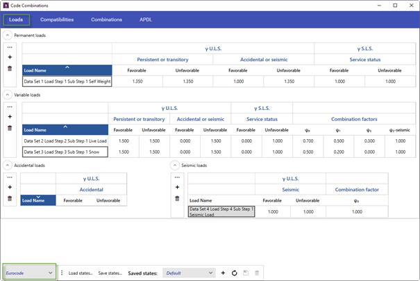
From the Loads tab, the actions are entered with their corresponding editable coefficients γ, ψ (favorable/unfavourable effect partials and simultaneous actions). User can add as many loads as needed.
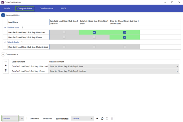
Incompatibilities between actions may occur:
1. Two loads are incompatible with each other when it cannot be the case that the two appear in any combination together.
2. A dominant load is incompatible with another concomitant when it is not possible for the two to appear in any combination together.
In the same way, the concomitance between actions can be defined. All the charges that belong to a group of charges will appear together in the combinations, being all at the same time either dominant or concomitant.
Once the loads and the incompatibilities between them have been defined, the combinations can be calculated. In this section you can choose the types of combination that you want the program to carry out (ULS and SLS).
It will be possible to proceed with the previous generation of the combinations with the Generate Preview button.
The program warns that a high number of combinations can be generated and that extra resources from both CivilFEM and the computer can be consumed.
CivilFEM will create the combinations (with their corresponding new load steps) inside the results files (RST and RCV).
The list of combinations can be exported to a word file.
It is also available to save the configuration of actions performed within the window to an external file.
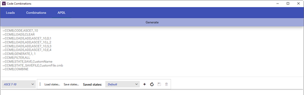
In the same way, the user will be able to access the APDL command lines that generate what has been done within the window in a script.
6.11.2 ASCE combinations of loads
If ASCE standards are chosen for the generation of load combinations then the process is simplified into two groups:
1. Design according to Strength Design.
2. Design according to Allowable Stress Design.
The selection of loads is the same as with the Eurocode, but here the type of load is selected according to dropdown lists: Dead, Live, Roof Live, Wind, Seismic, Rain, Snow.
The combining factored loads are automatically defined according to Basic Combinations of Strength Design or/and Allowable Stress Design.
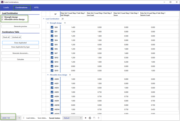
The list of combinations can be exported to a word file.
It is also available to save the configuration of actions performed within the window to an external file.
In the same way, the user will be able to access the APDL command lines that generate what has been done within the window in a script.