Cable-Stayed Bridges Generator
There are two types of cable arrangements: Harp and Fan.
Harp like arrangement

Fan like arrangement

Besides, both types include many more options:
o Symmetric or not
o Unlimited number of towers
o Vertical or inclined tower
o Tower of variable cross section
o Bridge deck with variable depth
In the generated bridge beam model all norms and conventions used in the Bridges Module are kept up and, as well, all utilities for load generation are applicable.
1 CABLE-STAYED BRIDGES GENERATION WINDOW
1.1 TYPOLOGIES
Only admissible the ones generated as CivilFEM Bridge Section, concrete box or slab type (only beam model).


1.2 USING THE GENERATOR
Before launching it, user must define the following data:
- Unit System.
- Materials to be used: concrete, steel, etc.
- Element types for bridge deck, towers, and cables.
- Bridge sections (deck)
- Cross sections (towers and cables)
- Beam & Shell Properties.
After that, the generator window appears with the ~BRCS, FileName command
or using the Main Menu path:
Civil Preprocessor > Bridges Prep > Predesigned bridges > Cable Stayed Bridges > Concrete

1.3 DATA EXPLANATION
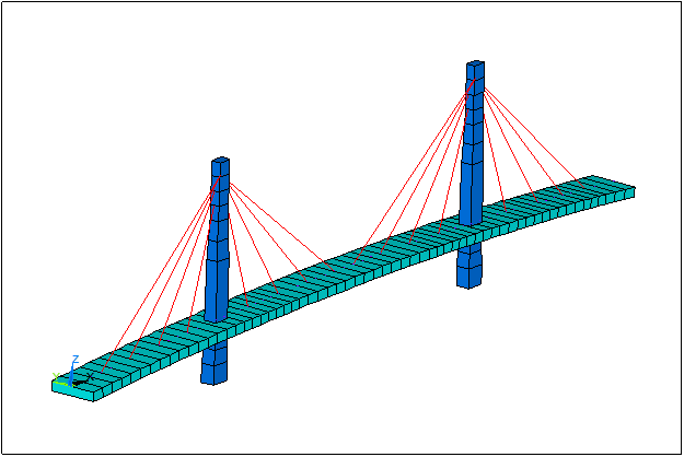
Referring to the next figures (harp & fan types) the required geometric data are explained in the following chapters:


1.3.1 GENERAL PARAMETERS TAB

Basic and general data will be introduced, to be constant in all model:
General Parameters:
|
NTow |
Number of towers |
|
MaxES |
Maximum size of longitudinal division (SIZEL parameter of the ~BRGEN command |
|
Dil |
Dilatation, allows movement in X direction |
Element types & Materials:
|
Cable |
|
Deck |
|
Tower |
Deck Definition:
|
P1X, P1Z |
X, Z coordinates of initial point of bridge layout |
|
P2X, P2Z |
X, Z coordinates of final point of bridge layout |
|
P3X, P3Z |
X, Z coordinates of a third arbitrary point of bridge layout |
|
BrSec1 |
Initial section of bridge |
|
BrSec2 |
Final section of bridge |
Boundary Conditions (at P1, P2):
|
UX, UY, UZ |
Constrained movement along X, Y, Z axes |
|
ROTX, ROTY, ROTZ |
Constrained rotation about X, Y, Z axes |
|
All |
All DOFs constrained |
1.3.2 TOWERS TAB


Tower Properties:
|
ID |
Number of active tower |
|
Symmetric |
Symmetry from left to right in number, area and distance between cables and bridge |
|
Vertical |
Vertical active tower |
|
Layout: HARP or FAN |
Cable arrangement: Harp or Fan |
|
TowerSec |
Tower cross-section in tower-deck connection |
|
DeckSec |
Bridge section in tower-deck conection |
Number of cables:
|
Left, Right |
Number of cables at left and right of active tower |
End Points:
|
XBot, ZBot |
X, Z coordinates at bottom of active tower |
|
TSecBot |
Cross-section at bottom of active tower |
|
XTop, ZTop |
X, Z coordinates at top of active tower |
|
TSecTop |
Cross-section at top of active tower |
Deck Points:
|
XDistL,XDistR |
Arrays of X distances at left and right of active tower |
|
BrSecL, BrSecR |
Arrays of bridge sections at left and right of active tower |
|
CableAL, CableAR |
Cable areas at left and right of active tower |
Tower Points:
|
ZDistT,ZDistB |
Arrays of Z distances from top and bottom of active tower points where cross section vary or cable is attached |
|
TsecT, TsecB |
Arrays of cross-sections from top and bottom of active tower |
|
CableAL, CableAR |
Arrays of cable areas at left and right of active tower |
Boundary Conditions (at bottom & tower-deck connection):
|
UX, UY, UZ |
Constrained movement along X, Y, Z axes |
|
ROTX, ROTY, ROTZ |
Constrained rotation about X, Y, Z axes |
|
All |
All DOFs constrained |
Related commands: