

11-A.1 Introduction
The check and design process of reinforced concrete beams under axial loading plus biaxial bending is based on the 3D interaction diagram of the analysed transverse section. This 3D interaction diagram contains forces and moments (FX, MY, MZ) corresponding to the section’s ultimate strength states. Using this diagram, the program is able to check and design the section accounting for forces and moments previously obtained that act on the section. This process considers both generic sections and sections formed by different concretes and reinforcement steels.
The codes CivilFEM considers for the checking and design of reinforced beams subjected to axial force and biaxial bending are: ACI 318, EHE, Eurocode 2, British Standard 8110, Australian Standard 3600, CEB-FIP 1990 model code, the Chinese code GB50010, NBR6118, AASHTO Standard Specifications for Highway Bridges, Russian Code СП 52-101-03, Indian Standard IS 456 and ACI 349.
11-A.2 Predesign of Rectangular Sections
The purpose of this utility is to perform a predesign of the required reinforcement when the section is rectangular.
The method used for predesign is based on the theory of the limit moment (rectangular stress-strain diagram).
11-A.2.1 Notation
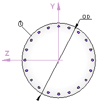
The notation used for the section’s geometry is shown in the figures below:

Notation for forces acting on the section:

The forces and moments always refer to the main section axes.
11-A.2.2 Load Cases
Depending on ![]() and
and ![]() values, different situations may occur. For every case, the limit
moment theory will be followed.
values, different situations may occur. For every case, the limit
moment theory will be followed.
11-A.2.2.1
Pure Bending 
Using the expression:
![]()
Two cases exist, depending on the value of the calculated moment.
Case a. - If ![]()
Compression reinforcement will not be necessary.
![]() (Tension)
(Tension)
Case b.- If ![]()
Tension reinforcement will not be necessary.
![]() (Compression)
(Compression)
![]() (Tension)
(Tension)
In all cases:
|
|
Design strength of concrete under compression. |
|
|
Design strength of reinforcement steel. |
11-A.2.2.2 Bending or Bending + Axial Load
Case a.- Design of compression reinforcement.
·
If ![]()
Compression reinforcement will not be necessary.
·
If ![]()
The compression reinforcement is:
![]() =
=![]()
Case b.- Design of tension reinforcement.
Once we have
reinforcement ![]() ,
, ![]() and
and ![]() can be defined as;
can be defined as;
![]()
![]()
·
If ![]()
This is a bending + axial load case:
![]()
·
If ![]()
In this case ![]() and therefore the program will take the minimum reinforcement.
and therefore the program will take the minimum reinforcement.
·
If ![]()
![]()
where

For this analysis to be correct,![]() ; otherwise if
; otherwise if ![]() is negative,
is negative, ![]() and the program will use the minimum considered reinforcement.
and the program will use the minimum considered reinforcement.
11-A.2.2.3
Tension ( )
)
In this case,
the most economical solution is obtained when both reinforcements reach the
calculated resistance (the point of application of the force ![]() coincides with the reinforcement center of gravity), obtaining:
coincides with the reinforcement center of gravity), obtaining:
![]()
![]()
where
![]()
11-A.2.3 Minimum Reinforcement
The minimum reinforcement amounts used by the program in the predesign commands (see the ~CALSERC and ~CLPRD commands) are detailed below:
· Minimum Mechanical Amount
|
|
More tension or less compression in the fiber |
More compression or less tension in the fiber |
|
Tension |
|
|
|
Compression |
|
|
|
Axial tension+bending |
|
|
|
Axial compression+bending |
|
|
|
Axial load + bending |
|
0 |
|
Bending |
|
0 |
where:
|
|
Design strength of reinforcement steel. |
|
|
Design strength of concrete. |
|
h |
Total depth of the cross section. |
|
b |
Total width of the cross section. |
· Minimum Geometrical Amount
The values taken for the minimum geometrical amounts are the following:
|
Type of Structural Element |
More tension or less compression in the fiber |
More compression or less tension in the fiber |
|
|
Columns |
|
|
|
|
Slabs |
|
|
|
|
Beams |
|
0.3 · 3.3‰ |
|
|
Wall |
Horizontal reinforcement |
|
0.3 · 4‰ |
|
Vertical reinforcement |
|
0.3 · 1.2‰ |
|
11-A.3 3D Interaction Diagram
11-A.3.1 Pivot Diagram

Figure 11-A.3‑1 Pivot Diagram
A pivot is a strain limit associated with a material and its position in the section. If the strain in a section’s pivot exceeds the limit for that pivot, the section will be considered as cracked. Thus, pivots establish the positions of the strain plane. In an ultimate strength state, the strain plane supports at least one pivot of the section.
In CivilFEM, pivots are defined as material properties and these properties (pivots) are extrapolated to all the section’s points, taken into account the material of each point. Therefore, for the section’s strain plane determination, the following pivots and their corresponding material properties will be considered:
|
A Pivot |
EPSmax. Maximum allowable strain in tension at any point of the section (largest value of the maximum strains allowable for each point of the section if there are different materials in the section). |
|
B Pivot |
EPSmin. Maximum allowable strain in compression at any point of the section (largest value of the maximum strains allowable for each point of the section). |
|
C Pivot |
EPSint. Maximum allowable strain in compression at the interior points of the section. |
Navier’s hypothesis is assumed for the determination of the strains plane. The strain’s plane is determined according to the following equation:
![]()
where:
|
e (y,z) |
Strain of a section point as a function of the Y, Z axes of the section. |
|
|
Strain in the origin of the section (center of gravity). |
|
|
Curvature in Z axis. |
|
|
Curvature in Y axis. |
In CivilFEM, the three elements eg, Kz, Ky are substituted by the elements
![]() ,
, ![]() , K to determine the strain plane. The relationship between (Kz, Ky)
and (q, K) is the following:
, K to determine the strain plane. The relationship between (Kz, Ky)
and (q, K) is the following:
![]() =
K·cos(q)
=
K·cos(q)
![]() =
K·sin(q)
=
K·sin(q)
q = Angle of the neutral axis with respect to the section’s Y axis

Figure 11-A.3‑2 Neutral Axis Location
11-A.3.2 Diagram Construction Process
As stated in the previous section, CivilFEM
uses the elements ![]() to determine the strains plane (ultimate strength plane) of the
section.
to determine the strains plane (ultimate strength plane) of the
section.
![]() and q are used as independent variables. The process is composed of the
following steps:
and q are used as independent variables. The process is composed of the
following steps:
1. Values of ![]() and q are chosen arbitrarily inside the extreme values allowed for these
variables, which are:
and q are chosen arbitrarily inside the extreme values allowed for these
variables, which are:
![]()
![]()
If there is no A pivot, (if there is no reinforcement steel or if ACI, AS3600 or BS8110 codes are used) the tension limit does not exist and is considered infinite.
2. From the angle q, the program can identify which points are inside and outside the nucleus of the section.
3. Once the interior and exterior points are known, the two extreme admissible strains, EPSmin and EPSmax, are defined in each of the points (for each point based on its material).
4. For each point of the section, the minimum ultimate strength curvature (K) is calculated.
5. The K curvature will be adopted as the minimum of all the curvatures of all the section points, according to the condition K ³ 0.
6. From the obtained K curvature and eg (strain imposed in the section’s center of gravity), the deformation corresponding to each of the section points e (x, y), is determined using the equations shown previously.
7. From the e (x, y) strain, the stress corresponding to each point of the section (sp) is calculated and entered into the stress-strain diagram for that point. Through this method, the stress distribution inside the section is determined.

Figure 11-A.3‑3 Stress determination at a point
1. Thus, as the elements![]() are determined, the ultimate forces and moments (FX, MY, MZ) corresponding
to the eg strain and the q angle defined
in step 1 are obtained by the summation of stresses at each of the section’s
points multiplied by its corresponding weight.
are determined, the ultimate forces and moments (FX, MY, MZ) corresponding
to the eg strain and the q angle defined
in step 1 are obtained by the summation of stresses at each of the section’s
points multiplied by its corresponding weight.


Where: NP = number of points of the section
![]() ,
, ![]() ,
, ![]() = weights at each point of the section.
= weights at each point of the section.
Note: For the design process, two components of forces and moments will be calculated: the component relating to the fixed points (corresponding to the reinforcement defined as fixed and to the concrete) and the component relating to the scalable points (corresponding to the part of the section reinforcement defined as scalable, see ~RNFDEF command). The final forces and moments will be equal to the sum of the forces and moments of both components. The forces and moments due to the component for scalable points will be multiplied by the reinforcement factor (w).
![]()
9. Steps 1 to 8 are repeated, adjusting the eg and q values and calculating the corresponding ultimate force and moments (FX, MY, MZ). Each defined couple (eg and q) represents a point in the 3D interaction diagram of the section. The greater the number of eg and q values used (inside the interval specified in step 1), the larger of the number of points in the diagram, and therefore the accuracy of the diagram will increase.
With all of the 3D points previously obtained, the program constructs the interaction diagram by calculating the convex hull of these points. Once the convex hull is calculated, the “convexity criterion” of the diagram is determined; this criterion is the minimum of the criteria calculated for all the points of the diagram. The ideal value of the convexity criterion of the diagram is 1. In CivilFEM, it is not recommended to perform the check and design described above with interaction diagrams whose convexity criterion is less than 0.95.
It has been proven that the interaction diagram of sections composed by materials whose stress-strain law (for sections analysis) presents a descending branch has a very low convexity criterion. The check and design process with the diagram of these sections may lead to unsafe solutions. Therefore, it is NOT RECOMMENDED to use materials with this characteristic.
11-A.3.3 Determination of the Diagram Center
Normal interaction diagrams contain the coordinates’ origin in their interior, but in some cases the origin may be a point belonging to the surface or even a point outside the diagram (such as for prestressed concrete sections). In this situation, the section is cracked for null forces and moments.
To avoid these situations, CivilFEM changes the axes, placing the origin of the coordinate system inside the geometric center of the diagram. In this case, the calculation of the safety criterion is executed according to the new coordinate’s origin instead of the real origin.
If these changes are not made, safety forces and moments (in the diagram interior) could have a safety factor less than 1.00 and vice versa. If the coordinate’s origin is close to the diagram’s surface (although still inside), it will also be necessary to change the origin coordinates. In these cases, although the safety factors maintain values greater than 1.0 for safe sections and less than 1.0 for unsafe ones, they may adopt arbitrary values not very related to the section’s real safety factor.
Therefore, CivilFEM establishes a criterion to determine whether to use the real coordinate system origin or a modified one as a reference. Thus, if the following condition is fulfilled, the origin of the coordinates will be modified, moving the diagram’s real center to its geometric center.
![]()
Where:
|
Distance |
Minimum distance from any point of the diagram to the real coordinate system origin. |
|
Delta |
Variable parameter which may be defined inside the [0,1] range. By default Delta=0.05. |
|
Diameter |
Diagonal of the rectangle which involves the diagram surface points. |
11-A.3.4 Considerations
- The selection of the strains values at the origin of the section (eg) inside the interval (EPSmin, EPSmax) for each adopted angle of the neutral axis (q) is made uniformly spaced for sections with reinforcements below the center of gravity (bottom reinforcement). Half of it is distributed in the tension zone and the other half in the compression zone, avoiding a concentration of points in the ultimate tension zone and obtaining an even distribution of points.
- If the section does not have bottom reinforcement for each q or the reinforcement does not have pivot (EPSmax) (as in the case of the ACI or BS8110 codes), the distribution of the tension zone is hyperbolic. The compression zone will continue to have uniform distribution. By default the number of the values adopted by eg is 30. The number of values must be a multiple of 2.
- At the same time, the selection of the q values is also uniform, inside the interval (-180º, +180º). The number of values must be a multiple of 4 in order to embrace the 4 quadrants of the section. By default, the number of values adopted by the program is 28.
- Although the number of the values of eg and q used for the construction of the diagram can be defined by the user, it is recommended to choose numbers close to the default values. These values have been chosen in consideration of the calculation time and precision. If a number of values for either variable is a great deal higher than the default value, the processing time increases significantly.
- On the other hand, if the number of values of eg and q is reduced significantly, the precision in the calculation of the diagram may be affected.
11-A.4 Axial Load and Biaxial Bending Checking
11-A.4.1 Hypothesis Calculation
· This checking procedure only verifies the section’s strength requirements; thus, requirements relating to serviceability conditions, minimum reinforcement amounts or reinforcement distribution for each code and structural typology will be not be considered.
· Navier’s hypothesis is always assumed as valid; therefore, the deformed section will remain plane. The longitudinal strain of concrete and steel will be proportional to the distance from the neutral axis.
11-A.4.2 Calculation Process
Checking elements for axial force and biaxial bending adheres to the following steps:
1. Obtaining the acting forces and moments of the section (FXd, MYd, MZd). The acting forces and moments are obtained, following a calculation, directly from the CivilFEM results file (file .RCV).
2. Constructing the interaction diagram of the section. The ultimate strain state is determined such that the ultimate forces and moments are homothetic to the acting forces and moments with respect to the diagram center.

Figure 11-A.4‑1 Determination of the homothetic strain state
3. Obtaining the strength criterion of the section. This criterion is defined as the ratio between two distances. As shown above, the distance to the “center” of the diagram (point A of the figure) from the point representing the acting forces and moments (point P of the figure) is labeled as d1 and the distance to the center from the point representing the homothetic ultimate forces and moments (point B) is d2.
![]()
If this criterion is less than 1.00, the forces and moments acting on the section will be inferior to its ultimate strength, and the section will be safe. On the contrary, for criterion larger than 1.00, the section will not be considered as valid.
11-A.5 Axial Load and Biaxial Bending Design (Reinforcement Factor)
11-A.5.1 Calculation Hypothesis
For the design of sections under axial loading and biaxial bending, the same hypothesis for the axial load and biaxial bending check is adopted.
11-A.5.2 Calculation Process
For the design, an optimization process is carried out through successive iterations; within this process, the safety factor of the section (or its criterion) must be strict (»1.00). These values are determined by the following steps:
1. Obtaining the minimum and maximum reinforcement factors. The maximum and minimum reinforcement factors (wmax ,wmin) are introduced by the user into the WMIN and WMAX fields from the ~DIMCON command. The designed reinforcement of the section will always be more than wmin times and less than wmax times the initial distribution.
2. Obtaining the reinforcement data of the section. The reinforcements of the section to be designed must be defined by the class (only reinforcements defined as scalable are modified), type, position and initial amount (see ~RNFDEF and ~RNFMDF commands). The designed reinforcement will be homothetic to the one defined in the section, in such a way that it complies with the strength requirements of the section. If the reinforcement amount is null, the program will not perform the design.
3. Obtaining the forces and moments acting on the section. Forces and moments (FX, MY, MZ) acting on the section are obtained directly from the CivilFEM results file (file .RCV).
4. Constructing the 3D interaction diagram. The diagram of the section is constructed for reinforcement corresponding to wmin times the initial distribution to determine the ultimate forces and moments of the section with this configuration.
![]()
5. From the interaction diagram of the previous step the ultimate strain state homothetic to the acting forces and moments can be determined with respect to the diagram center.
6. Obtaining the strength criterion of the section. This criterion is determined following the same process as described in the checking section.
7.
If the value of the criterion is less than
1.00 (the forces and moments acting on the section are inferior to its ultimate
strength), the section will be assigned reinforcement equal to ![]() times the initial distribution and the
calculation will be terminated.
times the initial distribution and the
calculation will be terminated.
8.
Repetition of steps 4, 5 and 6 for a
reinforcement corresponding to ![]() times the initial reinforcement distribution.
times the initial reinforcement distribution.
![]()
9. If the value of the strength criterion of the section is more than 1.00 (acting forces are larger than the ultimate strength of the section), the program will indicate it is not possible to design the section and will not assign reinforcement nor will it continue calculating.
10. Optimization of the section reinforcement through successive iterations. From the forces and moments previously determined (FX, MY, MZ)fixed and (FX, MY, MZ)scalable, a search is done to obtain a reinforcement factor w that will produce a value of the section criterion between 0.99 and 1.01. The program will then assign reinforcement equal to w times the initial distribution of the section.
11-A.6 Axial Load and Biaxial Bending Design (Reinforcement Amount)
11-A.6.1 Calculation Hypothesis
For the design of sections under axial loading and biaxial bending, the same hypothesis for the axial load and biaxial bending check is adopted.
11-A.6.2 Calculation Process 2D
For the design, an optimization process is carried out through successive iterations; within this process, the safety factor of the section (or its criterion) must be strict (»1.00) with the minimum reinforcement amount:
1. Obtaining the reinforcement data of the section and the minimum and maximum reinforcement. To do this, the data of the reinforcement groups of the defined section are obtained. Only scalable reinforcement groups (up to a maximum of four) will be designed. The mechanical cover is taken from the one defined in the reinforcement group and the amount defined is used as a starting point for the reinforcement optimization process.
The maximum wmax and minimum wmin reinforcement factors can be given by the user in the WMIN and WMAX fields of the ~DIMCON command. The amount defined in the reinforcements in the section and these factors will determine the maximum and minimum reinforcement.
If the WMIN and WMAX values are not entered in the command, the program determines a minimum reinforcement amount equal to the area of 2 rounds of phi = 12mm and a maximum reinforcement amount equal to 10% of the section area. In this case, during the reinforcement optimization process, it is allowed to return an amount of zero in the event that it is more optimal to dimension without that reinforcement group than with the default minimum.
2. Obtaining the forces and moments acting on the section. Forces and moments (FX, MY, MZ) acting on the section are obtained directly from the CivilFEM results file (file .RCV).
3. Optimization of the reinforcement of the section through successive iterations. First of all, a design is carried out using the reinforcement factor method (see 11-A.5). Starting from this new reinforcement (which meets the criterion of 1 but does not have to be the minimum), an iterative process is carried out in which each reinforcement group is decreased and the rest of the reinforcements are calculated using the factor of reinforcement so that, maintaining the criterion of 1, the least amount of total armor is achieved.
Notes:
- If two reinforcement groups are defined on the same face, an attempt is made to dimension only the reinforcement group with a smaller cover. If the maximum is reached, it is redesigned again taking into account the other reinforcement group, leaving the maximum amount to the reinforcement group with less coverage.
- Reinforcement groups parallel to the axis of the moment are not taken into account for sizing in this moment, giving a result of zero in that reinforcement amount.
11-A.6.3 Calculation Process 3D
For the reinforcement calculation in the 3D case, a 2D design is first carried out in each direction. Once the reinforcements have been obtained for each direction, a 3D reinforcement factor is made with combinations of the reinforcements obtained in each direction, resulting in the combination that, multiplied by its 3D reinforcement factor, results in a smaller amount.
11-A.7 Calculation Codes
For the check and design of reinforced concrete beams with different codes, the only variation will be the consideration of the pivots relative to the concrete (corresponding to EPSmin) and to the steel (corresponding to EPSmax). Therefore the pivots diagram for each code will differ in the construction of the section interaction diagram.
Codes provided by CivilFEM for the check and design of reinforced concrete beams under axial load and biaxial bending include: Eurocode 2, Spanish code EHE, American codes ACI 318 and ACI 349, British Standard 8110, Australian Standard 3600, CEB-FIP model code, Chinese code GB50010, Brazilian code NBR6118, AASHTO Standard Specifications for Highway Bridges and ITER Structural Design Code for Buildings.
The strain limits defined hereafter are default values, but can be changed for each of the materials defined in the model.
11-A.7.1 Eurocode 2 and ITER Design Code
If the active code is Eurocode 2 or ITER Structural Design Code for Buildings, the strain states relative to concrete and reinforcement steel are those defined in the following figure:

Figure 11-A.6‑1 Eurocode 2 Strain Limits for fck < 50 Mpa
If concrete has ![]() , the concrete strain limits are the following:
, the concrete strain limits are the following:
EPSmin (‰)
= ![]()
EPSint (‰) = ![]()
11-A.7.2 EHE
If the active code is EHE, the strain states relative to concrete and reinforcement steel are those defined in the following figure:

Figure 11-A.6‑2 EHE Strain Limits for fck < 50 Mpa
If concrete has fck > 50 MPa, the concrete strain limits are the following:
EPSmin (‰) = -(2.6+14.4[(100-fck)/100]4) (with fck in MPa).
EPSint (‰) = -(2.0+0.085(fck-50)0.5) (with fck in MPa).
11-A.7.3 ACI 318-05
If the active code is ACI 318-05, the strain states relative to concrete and reinforcement steel are those defined in the following figure. It can be noted that there is no pivot relative to steel (EPSmax), considering the section does not fail due to reinforcement steel deformation.

Figure 11-A.6‑3 ACI 318-05 Strain Limits
The theoretical values of the interaction diagram are affected by the strength reduction factor f according to Chapter 9.3 of Building Code Requirements for Structural Concrete Structures (ACI 318-05) document. This value is taken from the member properties if the user has specified a constant value or is calculated according to the code as follows (if the member property is not defined or the value is set as 0.0):

![]()
![]()
![]()
![]()
![]()
Where et is the maximum strain obtained at the reinforcement and ![]() is the strength
reduction factor for compression controlled sections:
is the strength
reduction factor for compression controlled sections:
Member with spiral
reinforcement ![]() =0.70
=0.70
Other reinforcement members ![]() =0.65 (default value)
=0.65 (default value)
(Defined in ~CHKCON and ~DIMCON commands)
Furthermore, according to Chapter 10.3.6 of Building Code Requirements for Structural Concrete Structures (ACI 318-05) document, design axial strength ϕPn of compression members must not be greater than:
1. For member with spiral reinforcement:
![]()
2. For other reinforcement:
![]()
Where Ag is the gross area of concrete section and Ast is the total area of longitudinal reinforcement.
11-A.7.4 CEB-FIP
If the active code is CEB-FIP, the strain states relative to concrete and reinforcement steel are those defined in the following figure:

Figure 11-A.6‑4 CEB-FIP Strain Limits
11-A.7.5 BS8110
If the active code is BS8110, the strain states relative to concrete and reinforcement steel are those defined in the following figure. It can be noted that there is no pivot relative to steel (EPSmax), considering the section does not fail due to reinforcement steel deformation:

Figure 11-A.6‑5 British Standard 8110 Strain Limits
11-A.7.6 AS3600
If the active code is AS3600, CivilFEM uses the same parameters as the ACI 318 code for material properties.
The theoretical values of the interaction diagram are affected by the strength reduction factor f. This value is taken from the member properties.
11-A.7.7 GB50010
If the active code is GB50010, the strain states relative to concrete and reinforcement steel are the ones defined in the following figure:

Figure 11-A.6‑6 GB50010 Strain Limits
Where EPScu = 0.0033-(fcuk-50)*105 [MPa]
11-A.7.8 NBR6118
If the active code is NBR6118, the strain states relative to concrete and reinforcement steel are those defined in the following figure:

Figure 11-A.6‑7 NBR6118 strain limits
11-A.7.9 AASHTO Standard Specifications for Highway Bridges
If the active code is AASHTO Standard Specifications for Highway Bridges, CivilFEM uses the same parameters as the ACI 318 code for material properties.
The theoretical values of the interaction diagram are affected by the strength reduction factor f. This value is taken from the member properties if the user has specified a desired constant value or is calculated according to the code as follows (if the member property is not defined or the value is set as 0.0):
![]()
![]()
![]()
![]()
![]()
Where et is the maximum strain obtained at the reinforcement.
11-A.7.10 IS 456
If the active code is the Indian Standard 456, the strain states relative to concrete are the ones defined in the following figure:

Figure 11-A.6‑8 IS 456 strain limits
It can be noted that there is no pivot relative to steel (EPSmax), considering the section does not fail due to reinforcement steel deformation.
11-A.7.11 SP 52-101
If the active code is SP 52-101, the strain states relative to concrete and reinforcement steel are the ones defined in the following figure:

Figure 11-A.6‑9 SP 52-101 strain limits
11-A.7.12 SP 63.13330.2012
If the active code is SP 63.13330.2012, the strain states relative to concrete and reinforcement steel are the ones defined in the following figure:

Figure 11-A.6‑10 SP 63.13330.2012 strain limits
11-A.7.13 ACI 349-01
If the active code is ACI 349-01, the strain states relative to concrete and reinforcement steel are the ones defined in the following figure. It can be noted that there is no pivot relative to steel (EPSmax), considering the section does not fail due to reinforcement steel deformation.

Figure 11-A.6‑11 ACI 349-01 strain limits
The theoretical values of the interaction diagram are affected by the strength reduction factor f (Chapter 9.3.2 of Code Requirements for Nuclear Safety Related Concrete Structures (ACI 349-01) document ). This value is taken from the member properties if the user has specified a constant value or is calculated according to the code as follows (if the member property is not defined or the value is set as 0.0):
![]()
![]()
![]()
![]()
![]()
![]()
Where ![]() is the axial load (tension positive),
is the axial load (tension positive), ![]() is the concrete gross area and
is the concrete gross area and ![]() is the strength reduction factor for compression controlled
sections:
is the strength reduction factor for compression controlled
sections:
Member with spiral
reinforcement ![]() =0.75
=0.75
Other reinforcement members ![]() =0.70 (default value)
=0.70 (default value)
(Defined in ~CHKCON and ~DIMCON commands)
Furthermore, according to Chapter 10.3.5 of Code Requirements for Nuclear Safety Related Concrete Structures (ACI 349-01) document, design axial strength ϕPn of compression members must not be greater than:
1. For member with spiral reinforcement:
![]()
2. For other reinforcement:
![]()
Where Ag is the gross area of concrete section and Ast is the total area of longitudinal reinforcement.
11-A.7.14 ACI 318-14
If the active code is ACI 318-14, the strain states relative to concrete and reinforcement steel are those defined in the following figure. It can be noted that there is no pivot relative to steel (EPSmax), considering the section does not fail due to reinforcement steel deformation.

Figure 11-A.6‑12 ACI 318-14 Strain Limits
The theoretical values of the interaction diagram are affected by the strength reduction factor f according to Chapter 21.2.2 of Building Code Requirements for Structural Concrete Structures (ACI 318-14) document. This value is taken from the member properties if the user has specified a constant value or is calculated according to the code as follows (if the member property is not defined or the value is set as 0.0):

![]()
![]()
![]()
![]()
![]()
Where et is the maximum strain obtained at the reinforcement and ![]() is the strength
reduction factor for compression controlled sections (21.2.2 of ACI 318 2014):
is the strength
reduction factor for compression controlled sections (21.2.2 of ACI 318 2014):
Member with spiral
reinforcement ![]() =0.75
=0.75
Other reinforcement members ![]() =0.65 (default value)
=0.65 (default value)
(Defined in ~CHKCON and ~DIMCON commands)
Furthermore, according to Chapter 22.4.2 of Building Code Requirements for Structural Concrete Structures (ACI 318-14) document, design axial strength ϕPn of compression members must not be greater than:
1. For member with spiral reinforcement:
![]()
2. For other reinforcement:
![]()
Where Ag is the gross area of concrete section and Ast is the total area of longitudinal reinforcement.
11-A.7.15 ACI 318-19
If the active code is ACI 318-19, the strain states relative to concrete and reinforcement steel are those defined in the following figure. It can be noted that there is no pivot relative to steel (EPSmax), considering the section does not fail due to reinforcement steel deformation.

The theoretical values of the interaction diagram are affected by the strength reduction factor f according to Chapter 21.2.2 of Building Code Requirements for Structural Concrete Structures (ACI 318-19) document. This value is taken from the member properties if the user has specified a constant value or is calculated according to the code as follows (if the member property is not defined or the value is set as 0.0):

![]()
![]()
![]()
![]()
![]()
Where:
![]() with
E = 29.000.000 psi
with
E = 29.000.000 psi
et is the maximum strain obtained at
the reinforcement and ![]() is the strength reduction factor for compression controlled
sections (21.2.2 of ACI 318
2019):
is the strength reduction factor for compression controlled
sections (21.2.2 of ACI 318
2019):
Member with spiral
reinforcement ![]() =0.75
=0.75
Other reinforcement members ![]() =0.65 (default value)
=0.65 (default value)
(Defined in ~CHKCON and ~DIMCON commands)
Furthermore, according to Chapter 22.4.2 of Building Code Requirements for Structural Concrete Structures (ACI 318-19) document, design axial strength ϕPn of compression members must not be greater than:
1. For member with spiral reinforcement:
![]()
2. For other reinforcement:
![]()
Where Ag is the gross area of concrete section and Ast is the total area of longitudinal reinforcement.
11-A.7.16 ACI 349-06
If the active code is ACI 349-06, the strain states relative to concrete and reinforcement steel are the ones defined in the following figure. It can be noted that there is no pivot relative to steel (EPSmax), considering the section does not fail due to reinforcement steel deformation.

Figure 11-A.6‑13 ACI 349-01 strain limits
The theoretical values of the interaction diagram are affected by the strength reduction factor f (Chapter 9.3.2 of Code Requirements for Nuclear Safety-Related Concrete Structures (ACI 349-06) document). This value is taken from the member properties if the user has specified a constant value or is calculated according to the code as follows (if the member property is not defined or the value is set as 0.0):

![]()
![]()
![]()
![]()
![]()
Where et is the maximum strain obtained at the reinforcement and ![]() is the strength
reduction factor for compression controlled sections:
is the strength
reduction factor for compression controlled sections:
Member with spiral
reinforcement ![]() =0.70
=0.70
Other reinforcement members ![]() =0.65 (default value)
=0.65 (default value)
(Defined in ~CHKCON and ~DIMCON commands)
Furthermore, according to Chapter 10.3.6 of Code Requirements for Nuclear Safety Related Concrete Structures (ACI 349-06) document, design axial strength ϕPn of compression members must not be greater than:
1. For member with spiral reinforcement:
![]()
2. For other reinforcement:
![]()
Where Ag is the gross area of concrete section and Ast is the total area of longitudinal reinforcement.
11-A.7.17 ACI 349-13
If the active code is ACI 349-13, the strain states relative to concrete and reinforcement steel are the ones defined in the following figure. It can be noted that there is no pivot relative to steel (EPSmax), considering the section does not fail due to reinforcement steel deformation.
Figure 11-A.6‑14 ACI 349-01 strain limits
The theoretical values of the interaction diagram are affected by the strength reduction factor f (Chapter 9.3.2 of Code Requirements for Nuclear Safety-Related Concrete Structures (ACI 349-13) document). This value is taken from the member properties if the user has specified a constant value or is calculated according to the code as follows (if the member property is not defined or the value is set as 0.0):
![]()
![]()
![]()
![]()
![]()
Where et is the maximum strain obtained at the reinforcement and ![]() is the strength
reduction factor for compression controlled sections:
is the strength
reduction factor for compression controlled sections:
Member with spiral
reinforcement ![]() =0.75
=0.75
Other reinforcement members ![]() =0.65 (default value)
=0.65 (default value)
(Defined in ~CHKCON and ~DIMCON commands)
Furthermore, according to Chapter 10.3.6 of Code Requirements for Nuclear Safety Related Concrete Structures (ACI 349-13) document, design axial strength ϕPn of compression members must not be greater than:
1. For member with spiral reinforcement:
![]()
2. For other reinforcement:
![]()
Where Ag is the gross area of concrete section and Ast is the total area of longitudinal reinforcement.
11-A.8 Previous Considerations to Shear and Torsion Calculation
11-A.8.1 Valid Sections for Shear and Torsion Checking
Valid reinforced concrete sections for shear and torsion check and design are the following:
Table 11-A.7‑1 Valid Sections for Shear and Torsion Checking
|
SECTION |
Y SHEAR |
Z SHEAR |
TORSION |
|
Rectangular |
Yes |
Yes |
Yes |
|
Box |
Yes |
Yes |
Yes |
|
Circular |
Yes |
Yes |
Yes |
|
Annular |
Yes |
Yes |
Yes |
|
Double T/ I-Section |
Yes |
No |
No |
|
T |
Yes |
No |
No |
For each one of these sections and directions, a set of geometrical parameters in accordance with the code is automatically defined. These parameters are required for the calculating process. Later on, there is a detailed explanation on how to obtain these parameters for each valid section.
In order to obtain these parameters a hypotheses group is adopted. The user can modify the parameters in this group with the ~SECMDF command
Parameters for invalid concrete sections will be undefined, and therefore, check and design commands will be unable to analyze these sections.
Sections that have undefined parameters are those that do not satisfy code hypotheses. However, these codes include some information for calculating those sections; as a result, the user can use the ~SECMDF command to freely define the undefined fields using appropriated values to complete the calculations.
11-A.8.2 Code Dependent Parameters
Parameters required for the check and design processes for shear and torsion are the following:
Eurocode 2 and ITER
|
REC: |
Reinforcement cover. |
||||||
|
BW_VY: |
Minimum width of the section over the effective depth for shear in Y. |
||||||
|
BW_VZ: |
Minimum width of the section over the effective depth for shear in Z. |
||||||
|
DY: |
Effective depth of the section in the Y direction. |
||||||
|
DZ: |
Effective depth of the section in the Z direction. |
||||||
|
RHO1: |
Reinforcement ratio:
Where:
|
||||||
|
T: |
Equivalent thickness of the wall:
Where:
This equivalent thickness cannot be greater than the real thickness of the wall nor less than twice the cover. |
||||||
|
AK: |
Area enclosed within the centre-line of the thin-walled cross-section. |
||||||
|
UK: |
Circumference of the AK area. |
||||||
|
KEYAST: |
Indicator of the position of the torsion reinforcement in the section: |
||||||
|
|
= 0 if closed stirrups are placed on both faces of each wall of the equivalent hollow section or on each wall of a box section (value by default for hollow sections). |
||||||
|
|
= 1 if there are only closed stirrups distributed around the periphery of the member (value by default for solid sections). |
||||||
|
THETA: |
Angle of the concrete compressive struts with the longitudinal axis of member. |
ACI 318 and ACI349
|
REC: |
Reinforcement cover. |
|
BW_VY: |
Web width or diameter of circular section for shear in Y (Art. 11.1). |
|
BW_VZ: |
Web width, or diameter of circular section for shear in Z (Art. 11.1). |
|
DY: |
Distance from extreme compression fiber to centroid of longitudinal tension reinforcement in Y, (for circular sections, this distance should not be less than the distance from extreme compression fiber to centroid of tension reinforcement in the opposite half of the member) (Art. 11.1). |
|
DZ: |
Distance from extreme compression fiber to centroid of longitudinal tension reinforcement in Z, (for circular sections, this distance should not be less than the distance from extreme compression fiber to centroid of tension reinforcement in the opposite half of the member) (Art. 11.1). |
|
ACP: |
Area enclosed by outside perimeter of concrete cross section (Art. 11.6.1). |
|
PCP: |
Outside perimeter of the concrete cross section (Art. 11.6.1). |
|
AOH: |
Area enclosed by center-line of the outermost closed transverse torsional reinforcement (Art. 11.6.3). |
|
PH: |
Perimeter of centerline of outermost closed transverse torsional reinforcement (Art. 11.6.3). |
|
AO: |
Gross area enclosed by shear flow path (Art. 11.6.3). |
|
RHOW: |
Ratio of tensile reinforcement to Bw*d (ACI 318-2019) |
EHE
|
REC: |
Reinforcement cover. |
||||||
|
BW_VY: |
Width of element in VY direction equal to the total width in solid sections or in case of box sections, the width equals the sum of the width of both webs. |
||||||
|
BW_VZ: |
Width of element in VZ direction equal to the total width in solid sections or in case of box sections, the width equals the sum of the width of both webs. |
||||||
|
DY: |
Effective depth of the section in Y (Art. 44.2.3). |
||||||
|
DZ: |
Effective depth of the section in Z (Art. 44.2.3). |
||||||
|
RHO1: |
Geometric ratio of the longitudinal tensile reinforcement anchored at a distance greater than or equal to d (Art. 44.2.3.2).
Where:
|
||||||
|
HE: |
Equivalent thickness of the wall (Art. 45.2.1):
Where:
This equivalent thickness cannot be greater than the real thickness of the wall nor less than twice the cover. |
||||||
|
AE: |
Area inside the center-line of the design effective hollow section (Art. 45.2.2). |
||||||
|
UE: |
Perimeter of the center-line of the design effective hollow section (Art. 45.2.2). |
||||||
|
KEYAST: |
Indicator of the position of the torsion reinforcement in the section (Art. 45.2.2.1): |
||||||
|
|
=0 if closed stirrups are placed on both faces of each wall of the equivalent hollow section or of the real hollow section (value by default for hollow sections). |
||||||
|
|
= 1 if there are only closed stirrups distributed around the periphery of the member (value by default for solid sections). |
||||||
|
THETA: |
Angle of the concrete compressive struts with the longitudinal axis of member (Art. 44.2.3). |
|
REC: |
Reinforcement cover. |
|
BW_VY: |
Minimum web width, for shear in Y (Art.3.4.5.1 Part 1). |
|
BW_VZ: |
Minimum web width, for shear in Z (Art.3.4.5.1 Part 1). |
|
DY: |
Effective depth of section in the Y direction (Art.3.4.5.1 Part 1). |
|
DZ: |
Effective depth of section in the Z direction (Art.3.4.5.1 Part 1). |
|
AS: |
Longitudinal tension reinforcement (Art.3.4.5.4 Part 1). |
|
XW: |
Torsional modulus for checking and dimensioning purposes. |
|
X1: |
Minimum dimension of the rectangular torsion stirrups (Art.2.4.2 Part 2). |
|
Y1: |
Maximum dimension of the rectangular torsion stirrups (Art.2.4.2 Part 2). |
AS3600
|
REC: |
Reinforcement cover. |
|
BW_VY: |
Web width, or diameter of circular section for shear in Y (Art. 8.2.7.1). |
|
BW_VZ: |
Web width, or diameter of circular section for shear in Z (Art. 8.2.7.1). |
|
DO_Y: |
Distance from extreme compression fiber to centroid of longitudinal tension reinforcement in Y, (for circular sections, this distance should not to be less than the distance from extreme compression fiber to centroid of tension reinforcement in the opposite half of the member) (Art. 8.2.7.1). |
|
DO_Z: |
Distance from extreme compression fiber to centroid of longitudinal tension reinforcement in Z, (for circular sections, this distance should not to be less than the distance from extreme compression fiber to centroid of tension reinforcement in the opposite half of the member) (Art. 8.2.7.1). |
|
THETA: |
Angle of compression struts (Art. 8.2.10). |
|
AST: |
Area of flexural reinforcement in tension (Art. 8.2.7.1). |
|
AT: |
Area enclosed by center-line of the outermost closed transverse torsional reinforcement (Art. 8.3.5). |
|
UT: |
Perimeter of center-line of outermost closed transverse torsional reinforcement (Art. 8.3.6). |
|
JT: |
Torsional modulus (Art. 8.3.5). |
GB50010
|
REC: |
Reinforcement cover. |
|
BW_VY: |
Minimum width of the section over the effective depth for shear in Y (Art. 7.5.1). |
|
BW_VZ: |
Minimum width of the section over the effective depth for shear in Z (Art. 7.5.1). |
|
DY: |
Effective depth of the section in Y (Art. 7.5.1). |
|
DZ: |
Effective depth of the section in Z (Art. 7.5.1). |
|
HW_VY: |
Effective depth of the web in Y (Art. 7.5.1). |
|
HW_VZ: |
Effective depth of the web in Z (Art. 7.5.1). |
|
Acor: |
Area enclosed within the hoop reinforcements for torsion Ast1 (Art. 7.6.4). |
|
Acor1: |
Area enclosed within the hoop reinforcements for torsion Ast1 (Art. 7.6.4) of branch 1(e. x. Flange). |
|
Acor2: |
Area enclosed within the hoop reinforcements for torsion Ast1 (Art. 7.6.4) of branch 2(e. x. Flange). |
|
Ucor: |
Perimeter of the Acor area (Art. 7.6.4). |
|
Ucor1: |
Perimeter of the Acor1 area of branch 1 (Art. 7.6.4). |
|
Ucor2: |
Perimeter of the Acor2 area of branch 2 (Art. 7.6.4). |
|
Wt: |
Plastic resistance of torsion moment (Art. 7.6.4). |
|
Wt1: |
Plastic resistance of torsion moment of branch 1 (Art. 7.6.4). |
|
Wt2: |
Plastic resistance of torsion moment of branch 2 (Art. 7.6.4). |
|
ALF: |
Ratio of the web depth to the web width (Art. 7.6.1). |
|
ALFh: |
Affected factor of the thickness of web for torsion (Art. 7.6.6). |
|
Tky |
For rectangular sections: Section width in Y. |
|
Tkz |
For rectangular sections: Section width in Z. |
NBR6118
|
REC: |
Reinforcement cover. |
||||
|
BW_VY: |
Minimum width of the section over the effective depth for shear in Y (Art. 17.4.1.1.1). |
||||
|
BW_VZ: |
Minimum width of the section over the effective depth for shear in Z (Art. 17.4.1.1.1). |
||||
|
DY: |
Effective depth of the section in Y (Art. 17.4.2.2). |
||||
|
DZ: |
Effective depth of the section in Z (Art. 17.4.2.2). |
||||
|
HE: |
Equivalent thickness of the wall (Art. 17.5.1.4):
Where:
This equivalent thickness cannot be greater than the real thickness of the wall nor less than twice the cover. |
||||
|
AE: |
Area inside the centre-line of the design effective hollow section (Art. 17.5.1.4). |
||||
|
UE: |
Perimeter of the centre-line of the design effective hollow section (Art. 17.5.1.4). |
||||
|
THETA: |
Angle of the concrete compressive struts with the longitudinal axis of member (Art. 17.4.1.2.3). |
AASHTO Standard Specifications for Highway Bridges
|
REC: |
Reinforcement cover. |
|
BW_VY: |
Web width or diameter of circular section for shear in Y (Art. 8.15.5). |
|
BW_VZ: |
Web width or diameter of circular section for shear in Z (Art. 8.15.5). |
|
DY: |
Distance from extreme compression fiber to centroid of longitudinal tensile reinforcement in Y (for circular sections, this distance should not to be less than the distance from extreme compression fiber to centroid of tensile reinforcement in the opposite half of the member) (Art. 8.15.5). |
|
DZ: |
Distance from extreme compression fiber to centroid of longitudinal tensile reinforcement in Z, (for circular sections, this distance should not to be less than the distance from extreme compression fiber to centroid of tensile reinforcement in the opposite half of the member) (Art. 8.15.5). |
|
ACP: |
Area enclosed by outside perimeter of concrete cross section (taken from ACI 318 Art. 11.6.1). |
|
PCP: |
Outside perimeter of the concrete cross section (taken from ACI 318 Art. 11.6.1). |
|
AOH: |
Area enclosed by center-line of the outermost closed transverse torsion reinforcement (taken from ACI 318 Art. 11.6.3). |
|
PH: |
Perimeter of centerline of outermost closed transverse torsion reinforcement (taken from ACI 318 Art. 11.6.3). |
|
AO: |
Gross area enclosed by shear flow path (taken from ACI 318 Art. 11.6.3). |
IS 456
|
REC: |
Reinforcement cover. |
||||||
|
BW_VY: |
Minimum width of the section over the effective depth for shear in Y (Art. 40.1). |
||||||
|
BW_VZ: |
Minimum width of the section over the effective depth for shear in Z (Art. 40.1). |
||||||
|
DY: |
Effective depth of the section in Y (Art. 40.1). |
||||||
|
DZ: |
Effective depth of the section in Z (Art. 40.1). |
||||||
|
RHO1: |
Reinforcement ratio (Table 19):
Where:
|
||||||
|
Y1: |
Center to centre distance between corner bars situated between transversal stirrups, measured along Y axis of the transversal section. |
||||||
|
Z1: |
Centre to centre distance between corner bars situated between transversal stirrups, measured along Z axis of the transversal section. |
SP 52-101 and SP 63.13330.2012
|
REC: |
Reinforcement cover. |
|
BW_VY: |
Minimum width of the section over the effective depth for shear in Y. |
|
BW_VZ: |
Minimum width of the section over the effective depth for shear in Z. |
|
D_Y: |
Effective depth of the section in Y. |
|
D_Z: |
Effective depth of the section in Z. |
|
ZA: |
First length of the effective torsional section. |
|
ZB: |
Second length of the effective torsional section. |
11-A.8.3 Code Dependent Parameters Calculation for Each Section
The following section describes how to compute the required parameters for shear and torsion according to each code. Shear and torsion calculations are performed taking for each end its section for shear considerations without accounting for reductions or enlargements due to depth variations. The mechanical cover for bending longitudinal reinforcement is required for the calculations of some parameters. The default mechanical cover for every case is equal to 4 cm. However, each of the parameters can be modified as stated previously (see command ~SECMDF).
11-A.8.3.1 Rectangular Section Parameters
Calling Tky Section width in Y.
Tkz Section width in Z.

Eurocode 2 and ITER
|
|
|
|
|
|
|
|
|
|
|
|
|
|
|
|
|
|
ACI 318 and ACI 349
|
|
|
|
|
|
|
|
|
|
|
|
|
|
|
|
|
|
EHE
|
|
|
|
|
|
|
|
|
|
|
|
|
|
|
|
|
|
|
|
|
|
|
|
|
|
|
|
|
|
|
|
|
AS-3600
|
|
|
|
|
|
|
|
|
|
|
|
|
|
|
|
|
|
GB50010
|
|
|
|
|
|
|
|
|
|
|
|
|
|
|
|
|
|
|
|
|
|
|
|
|
|
|
|
|
|
|
|
|
|
|
|
|
|
|
|
|
|
|
|
|
AASHTO Standard Specifications for Highway Bridges
|
|
|
|
|
|
|
|
|
|
|
|
|
|
|
|
|
|
IS 456
|
|
|
|
|
|
|
|
|
|
|
|
|
|
|
SP 52-101 and SP 63.13330.2012
|
|
|
|
|
|
|
|
|
|
|
|
11-A.8.3.2 Box Section Parameters
Calling: Tky Section width in Y.
Tkz Section width in Z.
Twy Thickness of walls in Y.
Twz Thickness of walls in Z.

Eurocode 2 and ITER
|
|
|
|
|
|
|
|
|
|
|
|
|
|
|
|
|
|
ACI 318 and ACI 349
|
|
|
|
|
|
|
|
|
|
|
|
|
|
|
|
|
|
EHE
|
|
|
|
|
|
|
|
|
|
|
|
|
|
|
|
|
|
|
|
|
|
|
|
|
|
|
|
Ac = gross concrete area |
Xw is considered solid rectangular if Twy > 0.25Tky and Twz > 0.25Tkz.Otherwise: Xw = 2.MIN(Twy,Twz).(Tkay,Twy).(Tkz,Twz) |
|
X1 = MIN(Tky,Tkz) – 2.REC |
Y1 = MAX(Tky,Tkz) – 2.REC |
AS3600
|
REC = 0.04 m (by default) |
|
|
BW_VY = 2 · Twz |
BW_VZ = 2 · Twy |
|
DO_Y= Tky - REC |
DO_Z= Tkz – REC |
|
THETA= 45º |
AST= 0.002 · Ag Ag = gross area of the cross section |
|
AT = (Tky – 2·REC) · (Tkz – 2·REC) |
UT =2 [(Tky – 2·REC) + (Tkz – 2·REC)] |
|
JT=Xwt |
|
GB50010
|
REC = 0.04 m (by default) |
|
|
BW_VY = 2 Twz |
BW_VZ = 2 Twy |
|
DY= Tky – REC |
DZ = Tkz – REC |
|
HW_VY = Tky– 2´TWY |
HW_VZ = Tkz –2·TWZ |
|
Acor = (Tkz –2·REC) ·(Tky– 2·REC) |
Acor1= 0.0 |
|
Acor2= 0.0 |
Ucor = 2·(Tkz +Tky– 4·REC) |
|
Ucor1= 0.0 |
Ucor2= 0.0 |
|
|
|
|
|
|
|
|
|
NBR6118
|
|
|
|
|
|
|
|
|
|
|
|
|
|
|
AASHTO Standard Specifications for Highway Bridges
|
|
|
|
|
|
|
|
|
|
|
|
|
|
|
|
AO = 0.85 AOH
|
|
IS 456
|
|
|
|
BW_VY = 2 Twz |
BW_VZ = 2 Twy |
|
DY= Tky – REC |
DZ = Tkz – REC |
|
RHO1 = 0.0015 |
|
|
Y1 = Tky – 2·REC |
Z1 = Tkz – 2·REC |
SP 52-101 and SP 63.13330.2012
|
REC = 0.04 m (by default) |
|
|
BW_VY = 2 · Twz |
BW_VZ = 2 · Twy |
|
DY = Tky – REC |
DZ = Tkz – REC |
|
ZA = Tky |
ZB = Tkz |
11-A.8.3.3 Circular Section Parameters
Calling: OD Diameter of the section.
Eurocode 2 and ITER
|
|
|
|
BW_VY =2 · TKWALL |
BW_VZ =2 · TKWALL |
|
DY= OD - REC |
DZ = OD - REC |
|
RHO1 = 0.0015 |
|
|
|
|
|
KEYAST = 0 (inner and outer reinforcement). |
THETA = 45º |
ACI 318 and ACI 349
|
REC = 0.04 m (by default) |
|
|
BW_VY = OD |
BW_VZ = OD |
|
|
|
|
(In both directions, the distance from extreme compression fiber to centroid of reinforcement in the opposite half of the section is used, assuming that this reinforcement is uniformly distributed and considering the cover of REC.) |
|
|
|
|
|
|
|
|
AO = 0.85 AOH |
|


EHE
|
REC = 0.04 m (by default) |
|
|
|
|
|
DY = OD - REC |
DZ = OD - REC |
|
RHO1 = 0.0028 |
|
|
|
|
|
KEYAST = 1 (outer reinforcement) |
THETA = 45º |


|
REC = 0.04 m (by default) |
|
|
BW_VY = Tkz |
BW_VZ = Tky |
|
DY = Tky - REC |
DZ = Tkz - REC |
|
AS = 0.002.Ac |
|
|
X1 = OD – 2.REC |
Y1 = OD – 2.REC |
AS3600
|
REC = 0.04 m (by default) |
|
|
BW_VY = OD |
BW_VZ = OD |
|
|
|
|
(In both directions the distance from extreme compression fiber to centroid of reinforcement in the opposite half of the section is used, assuming that this reinforcement is uniformly distributed and considering the cover of REC.) |
|
|
THETA = 45º |
AST = 0.002 · Ag Ag = gross area of the cross section |
|
|
|
|
JT = Xwt |
|


GB50010
|
REC = 0.04 m (by default) |
|
|
BW_VZ = 0.88·OD |
BW_VY = 0.88·OD |
|
DY = 0.8·OD |
DZ = 0.8·OD |
|
HW_VY = 0.8·OD |
HW_VZ = 0.8·OD |
|
|
|
|
|
|
|
|
|
|
|
|
|
|
ALF = 0.91 |
|
|
|
|
REC = 0.04 m (by default) |
|
|
(The width of the square within the circumference is used) |
(The width of the square within the circumference is used) |
|
DY = OD - REC |
DZ = OD - REC |
|
|
|
|
|
THETA = 45º |
AASHTO Standard Specifications for Highway Bridges
|
REC = 0.04 m (by default) |
|
|
BW_VY = OD |
BW_VZ = OD |
|
|
|
|
(In both directions the distance from extreme compression fiber to centroid of reinforcement in the opposite half of the section is used, assuming that this reinforcement is uniformly distributed and considering the cover of REC.) |
|
|
|
|
|
|
|
|
AO = 0.85 AOH |
|
IS 456
|
|
|
|
(The width of the square within the circumference is used) |
(The width of the square within the circumference is used) |
|
DY = OD - REC |
DZ = OD - REC |
|
RHO1 = 0.0015 |
|
|
Y1 = OD – 2·REC |
Z1 = OD – 2·REC |
SP 52-101 and SP 63.13330.2012
|
|
|
|
(The width of the square within the circumference is used) |
(The width of the square within the circumference is used) |
|
DY = OD - REC |
DZ = OD - REC |
|
ZA = OD |
ZB = OD |
11-A.8.3.4 Circular Hollow Section Parameters
Calling: OD Diameter of the section.
TKWALL Thickness of the wall.

Eurocode 2 and ITER
|
REC = 0.04 m (by default) |
|
|
BW_VY =2 · TKWALL |
BW_VZ =2 · TKWALL |
|
DY= OD - REC |
DZ = OD - REC |
|
RHO1 = 0.0015 |
|
|
|
|
|
KEYAST = 0 (inner and outer reinforcement). |
THETA = 45º |
ACI 318 and ACI 349
|
REC = 0.04 m (by default) |
|
|
BW_VY = 2 · TKWALL |
BW_VZ = 2 · TKWALL |
|
|
|
|
(In both directions the distance from extreme compression fibre to centroid of reinforcement in the opposite half of the section is used, assuming that this reinforcement is uniformly distributed and considering the cover of REC.) |
|
|
|
|
|
|
|
|
AO = 0.85 AOH |
|
EHE
|
REC = 0.04 m (by default) |
|
|
|
|
|
|
|
|
DY = OD - REC |
DZ = OD - REC |
|
RHO1 = 0.0028 |
|
|
|
|
|
KEYAST = 0 (outer and inner reinforcement). |
THETA = 45º |


|
REC = 0.04 m (by default) |
|
|
BW_VY = 2 · TKWALL |
BW_VZ = 2 · TKWALL |
|
DY = OD - REC |
DZ = OD - REC |
|
AS = 0.002 . Ac |
XW is considered a solid circular section if (Tkwall > 0.25.OD) Otherwise:
|
|
X1 = OD - 2.REC |
Y1 = OD – 2.REC |
AS3600
|
REC = 0.04 m (by default) |
|
|
BW_VY = 2 · TKWALL |
BW_VZ = 2 · TKWALL |
|
|
|
|
(In both directions the distance from extreme compression fibre to centroid of reinforcement in the opposite half of the section is used, assuming that this reinforcement is uniformly distributed and considering the cover of REC.) |
|
|
THETA = 45º |
AST = 0.002 * Ag Ag = gross area of the cross section |
|
|
|
|
JT = Xwt |
|


GB50010
|
REC = 0.04 m (by default) |
|
|
BW_VY = 2 ·TKWALL |
BW_VZ = 2 ·TKWALL |
|
DY = 0.8·OD |
DZ = 0.8·OD |
|
HW_VY = not defined |
HW_VZ = not defined |
|
|
|
|
|
|
|
|
|
|
|
|
|
|
ALF = 0.91 |
|
|
|
|
REC = 0.04 m (by default) |
|
|
BW_VY =2 · TKWALL |
BW_VZ =2 · TKWALL |
|
DY = OD - REC |
DZ = OD - REC |
|
|
|
|
|
THETA = 45º |
AASHTO Standard Specifications for Highway Bridges
|
REC = 0.04 m (by default) |
|
|
BW_VY = 2 · TKWALL |
BW_VZ = 2 · TKWALL |
|
|
|
|
(In both directions the distance from extreme compression fibre to centroid of reinforcement in the opposite half of the section is used, assuming that this reinforcement is uniformly distributed and considering the cover of REC.) |
|
|
|
|
|
|
|
|
AO = 0.85 AOH |
|


IS 456
|
REC = 0.04 m (by default) |
|
|
BW_VY = 2 · TKWALL |
BW_VZ = 2 · TKWALL |
|
DY = OD - REC |
DZ = OD - REC |
|
RHO1 = 0.0015 |
|
|
Y1 = OD – 2·REC |
Z1 = OD – 2·REC |
SP 52-101 and SP 63.13330.2012
|
REC = 0.04 m (by default) |
|
|
BW_VY = 2 · TKWALL |
BW_VZ = 2 · TKWALL |
|
DY = OD - REC |
DZ = OD - REC |
|
ZA = OD |
ZB = OD |
11-A.8.3.5 Double T / I-Section Parameters
Calling: DEPTH Depth of the section (in Y).
TW Web thickness.

Eurocode 2 and ITER
|
REC = 0.04 m (by default) |
|
|
BW_VY = TW |
BW_VZ = undefined |
|
DY = DEPTH - REC |
DZ = undefined |
|
RHO1 = 0.0015 |
T = undefined |
|
AK = undefined |
UK = undefined |
|
KEYAST = undefined |
THETA = 45º |
ACI 318 and ACI 349
|
REC = 0.04 m (by default) |
|
|
BW_VY = TW |
BW_VZ = undefined |
|
DY = DEPTH - REC |
DZ = undefined |
|
ACP = undefined |
PCP = undefined |
|
AOH = undefined |
PH = undefined |
|
AO = undefined |
|
EHE
|
REC = 0.04 m (by default) |
|
|
BW_VY = TW |
BW_VZ = undefined |
|
DY = DEPTH - REC |
DZ = undefined |
|
RHO1 = 0.0028 |
HE = undefined |
|
AE = undefined |
U= undefined |
|
KEYAST = undefined |
THETA = 45º |
|
REC = 0.04 m (by default) |
|
|
BW_VY = Tkz |
BW_VZ = undefined |
|
DY = Tky - REC |
DZ = Tkz - REC |
|
AS = 0.002.Ac Ac = concrete gross section |
XW = undefined |
|
X1 = undefined |
Y1 = undefined |
AS3600
|
REC = 0.04 m (by default) |
|
|
BW_VY = TW |
BW_VZ = undefined |
|
DO_Y = DEPTH - REC |
DO_Z = undefined |
|
THETA = 45º |
AST = 0.002 · Ag Ag = gross area of the cross section |
|
AT= undefined |
UT = undefined |
|
JT = Xwt |
|
GB50010
|
REC = 0.04 m (by default) |
|
|
BW_VY = TW |
BW_VZ = undefined |
|
DY = DEPTH – REC |
DZ = undefined |
|
HW_VY = DEPTH – TFTOP – TFBOT |
HW_VZ = undefined |
|
|
|
|
|
|
|
|
|
|
|
|
|
|
|
|
|
|
NBR6118
|
REC = 0.04 m (by default) |
|
|
BW_VY = TW |
BW_VZ = undefined |
|
DY = DEPTH - REC |
DZ = undefined |
|
HE = undefined |
AE = undefined |
|
UE = undefined |
THETA = 45º |
AASHTO Standard Specifications for Highway Bridges
|
REC = 0.04 m (by default) |
|
|
BW_VY = TW |
BW_VZ = undefined |
|
DY = DEPTH - REC |
DZ = undefined |
|
ACP = undefined |
PCP = undefined |
|
AOH = undefined |
PH = undefined |
|
AO = undefined |
|
IS 456
|
REC = 0.04 m (by default) |
|
|
BW_VY = TW |
BW_VZ = undefined |
|
DY = DEPTH - REC |
DZ = undefined |
|
RHO1 = 0.0015 |
|
|
Y1 = DEPTH – 2·REC |
Z1 = TW – 2·REC |
SP 52-101 and SP 63.13330.2012
|
REC = 0.04 m (by default) |
|
|
BW_VY = TW |
BW_VZ = undefined |
|
DY = DEPTH - REC |
DZ = undefined |
|
ZA = DEPTH |
ZB = TW |
11-A.8.3.6 T Section Parameters
Calling: DEPTH Depth of the section (in Y).
TW Web thickness.

Eurocode 2 and ITER
|
REC = 0.04 m (by default) |
|
|
BW_VY = TW |
BW_VZ = undefined |
|
DY = DEPTH - REC |
DZ = undefined |
|
RHO1 = 0.0015 |
T = undefined |
|
AK = undefined |
UK = undefined |
|
KEYAST = undefined |
THETA = 45º |
ACI 318 and ACI 349
|
REC = 0.04 m (by default) |
|
|
BW_VY = TW |
BW_VZ = undefined |
|
DY = DEPTH - REC |
DZ = undefined |
|
ACP = undefined |
PCP = undefined |
|
AOH = undefined |
PH = undefined |
|
AO = undefined |
|
EHE
|
REC = 0.04 m (by default) |
|
|
BW_VY = TW |
BW_VZ = undefined |
|
DY = DEPTH - REC |
DZ = undefined |
|
RHO1 = 0.0028 |
HE = undefined |
|
AE = undefined |
U = undefined |
|
KEYAST = undefined |
THETA = 45º |
BS 8110
|
REC = 0.04 m (by default) |
|
|
BW_VY = Tkz |
BW_VZ = undefined |
|
DY = Tky - REC |
DZ = Tkz - REC |
|
AS = 0.002.Ac Ac = concrete gross section |
XW = undefined |
|
X1 = undefined |
Y1 = undefined |
AS3600
|
REC = 0.04 m (by default) |
|
|
BW_VY = TW |
BW_VZ = undefined |
|
DO_Y = DEPTH - REC |
DO_Z = undefined |
|
THETA = 45º |
AST = 0.002 · Ag Ag = gross area of the cross section |
|
AT = undefined |
UT = undefined |
|
JT = Xwt |
|
GB50010
|
REC = 0.04 m (by default) |
|
|
|
BW_VY = TW |
BW_VZ = TF |
|
|
DY = DEPTH – REC |
DZ = BF– REC |
|
|
HW_VY = DEPTH – TF – REC |
HW_VZ = undefined |
|
|
|
|
|
|
|
|
|
|
|
|
|
|
|
||
|
|
|
|
|
|
|
|
NBR6118
|
REC = 0.04 m (by default) |
|
|
BW_VY = TW |
BW_VZ = undefined |
|
DY = DEPTH - REC |
DZ = undefined |
|
HE = undefined |
AE = undefined |
|
UE = undefined |
THETA = 45º |
AASHTO Standard Specifications for Highway Bridges
|
REC = 0.04 m (by default) |
|
|
BW_VY = TW |
BW_VZ = undefined |
|
DY = DEPTH - REC |
DZ = undefined |
|
ACP = undefined |
PCP = undefined |
|
AOH = undefined |
PH = undefined |
|
AO = undefined |
|
IS 456
|
REC = 0.04 m (by default) |
|
|
BW_VY = TW |
BW_VZ = undefined |
|
DY = DEPTH - REC |
DZ = undefined |
|
RHO1 = 0.0015 |
|
|
Y1 = DEPTH – 2·REC |
Z1 = TW – 2·REC |
SP 52-101 and SP 63.13330.2012
|
REC = 0.04 m (by default) |
|
|
BW_VY = TW |
BW_VZ = undefined |
|
DY = DEPTH - REC |
DZ = DEPTH - REC |
|
ZA = DEPTH |
ZB = TW |
11-A.8.4 Calculation Hypotheses Common to Codes
· The shear, torsion and combined shear and torsion checks explained in the following paragraphs concentrates on reinforced concrete linear elements, beam or column type in 2D and 3D.
· Checking is only done for verifying the fulfilment of requirements concerning to the section’s strength requirements. Therefore, requirements referring to serviceability limit states, minimum reinforcement ratios or distribution depending on the code, environment, and structural typology are ignored.
· For shear checking, the shear reduction or increase due to depth variations is not considered. Therefore, sectional geometrical properties need to be constant within each member. However, this is not the reinforcement case, which may be defined for each section of each element.
· Other hypotheses or special considerations can be found in the explanation of the calculation process of each code.
11-A.9 Shear and Torsion according to Eurocode 2 (ENV 1992-1-1:1991)
11-A.9.1 Shear Checking
The shear checking of elements according to Eurocode 2 (ENV 1992-1-1:1991) is described in this section.
1) Obtaining the strength properties of the materials. The required material properties associated with each transverse cross section at the active time (see ~CFMP command) are:
![]() characteristic compressive strength of concrete.
characteristic compressive strength of concrete.
![]() design compressive strength of concrete.
design compressive strength of concrete.
![]() characteristic yield strength of reinforcement.
characteristic yield strength of reinforcement.
![]() design yield strength of reinforcement.
design yield strength of reinforcement.
2) Obtaining geometrical data of the section. Section geometrical requirements must be defined within the CivilFEM database, (~CSECDMS commands). Required data for shear checking:
Ac total cross-sectional area of the concrete section.
3) Obtaining geometrical parameters depending on specified code. Geometrical parameters used for shear calculations must be defined within the CivilFEM database, see ~SECMDF command. The required data:
![]() minimum width of the
section over the effective depth, (parameter BW_VY or BW_VZ of ~SECMDF command).
minimum width of the
section over the effective depth, (parameter BW_VY or BW_VZ of ~SECMDF command).
d effective depth of the section, (parameter D_Y or D_Z of ~SECMDF command).
![]() ratio of the longitudinal tensile reinforcement,
(parameter RHO1 of ~SECMDF command):
ratio of the longitudinal tensile reinforcement,
(parameter RHO1 of ~SECMDF command):
![]()
where:
![]() area of the tensile reinforcement extending not less than
area of the tensile reinforcement extending not less than ![]() beyond the section considered.
beyond the section considered.
q angle of the compressive struts of concrete with the longitudinal axis of member, (parameter THETA of ~SECMDF command):
![]() beams with constant longitudinal reinforcement
beams with constant longitudinal reinforcement
![]() beams with variable longitudinal reinforcement
beams with variable longitudinal reinforcement
Section 11-A.7 “Previous Considerations to Shear and Torsion Calculation” provides detailed information on how to calculate the required data for each code and valid section.
4) Obtaining reinforcement data of the section. Data concerning the reinforcement of the element section must be included within the CivilFEM database. (See ~RNFDEF and ~RNFMDF commands). Required data includes:
a angle between shear reinforcement and the longitudinal axis of the member section, (parameter ALPHA of ~RNFDEF or ~RNFMDF commands).
![]() area of reinforcement per unit length
(reinforcement ratio) in both the Y and Z directions, (These can be defined
directly using the ASSY and ASSZ parameters as part of the ~RNFDEF or ~RNFMDF
commands).
area of reinforcement per unit length
(reinforcement ratio) in both the Y and Z directions, (These can be defined
directly using the ASSY and ASSZ parameters as part of the ~RNFDEF or ~RNFMDF
commands).
The reinforcement ratio may also be obtained with the following data:
![]() total area of the reinforcement
legs, (parameters ASY and ASZ of ~RNFDEF or ~RNFMDF commands - both Y and Z directions are
available).
total area of the reinforcement
legs, (parameters ASY and ASZ of ~RNFDEF or ~RNFMDF commands - both Y and Z directions are
available).
s spacing of the stirrups, (parameter S of ~RNFDEF or ~RNFMDF commands).
or with the following ones:
s spacing of the stirrups, (parameter S of ~RNFDEF or ~RNFMDF commands).
f diameter of bars, (parameter PHI of ~RNFDEF or ~RNFMDF commands).
N number of reinforcement legs, (parameters NY or NZ of ~RNFDEF or ~RNFMDF commands for Y and Z directions).
5) Obtaining the section’s internal forces and moments. The shear force that acts on the section, as well as the concomitant axial force and bending moment, are obtained from the CivilFEM results file (.RCV).
Force Description
![]() Factored design shear force
Factored design shear force
![]() Factored design axial force (positive for compression)
Factored design axial force (positive for compression)
![]() Factored design bending moment
Factored design bending moment
6) Checking whether the section requires shear reinforcement. First, the design shear (![]() is compared to the design shear resistance(
is compared to the design shear resistance(![]() :
:
![]()
![]()
where:
![]() basic design shear strength, which, depending on the
different concrete strengths, has the following values in N/mm2:
basic design shear strength, which, depending on the
different concrete strengths, has the following values in N/mm2:
|
fck |
12 |
16 |
20 |
25 |
30 |
35 |
40 |
45 |
50 |
|
tRd |
0.18 |
0.22 |
0.26 |
0.30 |
0.34 |
0.37 |
0.41 |
0.44 |
0.48 |
For other values of ![]() , a linear interpolation is done. For values of
, a linear interpolation is done. For values of ![]() an interpolation is performed between 0 and 0.18. For values of
an interpolation is performed between 0 and 0.18. For values of ![]() ,
, ![]() always.
always.
![]() where d (in meters) is the effective depth of the section.
where d (in meters) is the effective depth of the section.
![]()
If shear
reinforcement has not been defined in the section, the design shear force (![]() ) is checked to be less than the maximum design shear force that can
be carried by the section without crushing the concrete compressive struts (
) is checked to be less than the maximum design shear force that can
be carried by the section without crushing the concrete compressive struts (![]() ):
):
![]()
![]()
where ![]() (
(![]() in
N/mm2)
in
N/mm2)
If the section
is subjected to a compressive axial force, ![]() should be reduced according to the equation below:
should be reduced according to the equation below:
![]()
where
![]() =
=![]() effective average stress in the concrete due to axial force.
effective average stress in the concrete due to axial force.
![]() is considered equal to zero (
is considered equal to zero (![]() is the reinforcement area in the compression zone in the ultimate
limit state).
is the reinforcement area in the compression zone in the ultimate
limit state).
Results are written for each end in the CivilFEM results file as the following parameters:
VRD1 Design shear resistance without considering the reinforcement.
![]()
CRVRD1 Ratio of
the design shear force (![]() ) to the resistance
) to the resistance ![]() .
.
![]()
For sections
subjected to a tensile axial force so that ![]() , then CRVRD1 is taken as 2100.
, then CRVRD1 is taken as 2100.
If shear reinforcement has not been defined, the results below are also given:
VRD2 Maximum design shear force that can be carried by the section without crushing of the concrete compressive struts. If the section is subjected to a compressive axial force, it will take the reduced value.
![]()
CRVRD2 Ratio of
the design shear force (![]() ) to the resistance
) to the resistance ![]() .
.
![]()
For sections
subjected to an applied compressive axial force so that ![]() , CRVRD2 is taken as 2100.
, CRVRD2 is taken as 2100.
7) Checking of elements requiring shear reinforcement. The shear resistance of a section with reinforcement (VRd3) is calculated with the standard method if q = 45º and with the variable strut inclination method if q ¹ 45º.
Conditions below must be verified:
![]()
![]()
![]() is the concrete
contribution to the shear resistance:
is the concrete
contribution to the shear resistance:
![]() standard method (q = 45º)
standard method (q = 45º)
![]() variable strut inclination method (q ¹ 45º)
variable strut inclination method (q ¹ 45º)
![]() is the shear reinforcement contribution to the shear
resistance.
is the shear reinforcement contribution to the shear
resistance.
The shear reinforcement contribution is given by the following equation:
![]()
with ![]() if the variable strut inclination method is applied.
if the variable strut inclination method is applied.
In this case,
the crushing of the concrete compressive struts ![]() is checked by the equation below:
is checked by the equation below:
![]()
For a shell vertex subjected to a compressive axial force, this value should be reduced in accordance with the criterion explained previously.
The tensile force in the longitudinal reinforcement is also calculated with the following expression:
![]()
where ![]() is the design bending moment occurring simultaneously with shear.
The second term of the equation represents the increase in tensile force with
respect to the value obtained with only the bending moment.
is the design bending moment occurring simultaneously with shear.
The second term of the equation represents the increase in tensile force with
respect to the value obtained with only the bending moment.
Results obtained are written for each end in the CivilFEM results file as the following parameters:
VWD Contribution of shear reinforcement to the shear resistance.
![]()
VRD3 Design shear resistance.
![]()
CRVRD3 Ratio of
the design shear force (![]() ) to the shear resistance
) to the shear resistance ![]() .
.
![]()
If ![]() , CRVRD3 is taken as
, CRVRD3 is taken as![]() .
.
For sections where shear reinforcements are defined, the parameters below are also written:
VRD2 Maximum design shear force that can be carried by the section without crushing of the concrete compressive struts. If the section is subjected to a compressive axial force, it will be defined with the reduced value.
![]()
CRVRD2 Ratio of
the design shear force (![]() ) to the resistance
) to the resistance ![]() .
.
![]()
If section is
subjected to a compressive axial force so that ![]() , then CRVRD2 is taken as
, then CRVRD2 is taken as![]() .
.
Tensile forces in the longitudinal reinforcement are stored in TENS parameter.
8) Obtaining shear criterion. The shear criterion indicates whether the section is valid for the design forces (if less than 1, the section satisfies the code provisions; if greater than 1, the section will not be valid). Furthermore, it includes information on how close the design force is to the ultimate section strength. The shear criterion is defined as follows:
![]()
For each end, this value is stored in the CivilFEM results file as the parameter CRT_TOT.
A value of ![]() for this criterion would mean that
for this criterion would mean that ![]() or
or ![]() are equal to zero.
are equal to zero.
11-A.9.2 Torsion Checking
Torsion checking according to Eurocode 2 (ENV 1992-1-1:1991) follows the steps below:
1) Obtaining strength properties of the materials. The required material properties associated with each transverse cross section at the active time (see ~CFMP command) are:
fck characteristic compressive strength of concrete.
fyk characteristic yield strength of reinforcement.
fyd design yield strength of torsional reinforcement (the same material is considered for transverse reinforcement and longitudinal reinforcement).
2) Obtaining geometrical parameters depending on specified code. Geometrical parameters used for torsion calculations must be defined within the CivilFEM database, (see ~SECMDF command). The required data:
t equivalent thickness of wall, (T parameter of ~SECMDF command).
![]() area enclosed within the centre-line of the thin-walled
cross-section, (AK parameter of ~SECMDF
command).
area enclosed within the centre-line of the thin-walled
cross-section, (AK parameter of ~SECMDF
command).
![]() circumference of area Ak, (UK parameter of ~SECMDF command).
circumference of area Ak, (UK parameter of ~SECMDF command).
KEYAST indicator of the position of torsional reinforcement in the section, (KEYAST parameter of ~SECMDF command):
0 if closed stirrups are placed in both faces of each wall of the equivalent hollow section or in each wall of a box section (value by default for hollow sections).
1 if there are closed stirrups only along the periphery of the member (value by default for solid sections).
q Angle of the compressive struts of concrete with the longitudinal axis of member, (parameter THETA of ~SECMDF command):
![]()
This is only taken into account if torsion reinforcement has not been defined. If reinforcement has been defined, q is calculated as explained below.
Section 11-A.7 “Previous Considerations to Shear and Torsion Calculation” provides detailed information on how to calculate the required data for each code and valid section.
3) Obtaining reinforcement data of the section. Data concerning reinforcements of the section must be included within the CivilFEM database, (see ~RNFDEF and ~RNFMDF commands). Required data are as follows:
Transverse Reinforcement
![]() area of transverse reinforcement per unit length, (can be
defined directly using the ASST parameter as part of the ~RNFDEF and ~RNFMDF
commands).
area of transverse reinforcement per unit length, (can be
defined directly using the ASST parameter as part of the ~RNFDEF and ~RNFMDF
commands).
The reinforcement ratio can alternatively be defined using the following data:
![]() closed stirrups area for torsion, (parameter AST of ~RNFDEF and ~RNFMDF
commands).
closed stirrups area for torsion, (parameter AST of ~RNFDEF and ~RNFMDF
commands).
s spacing of closed stirrups, (parameter S of ~RNFDEF and ~RNFMDF commands).
Or with the following data:
s spacing of closed stirrups, (parameter S of ~RNFDEF and ~RNFMDF commands).
![]() diameter of the closed stirrups, (parameter PHIT of ~RNFDEF and ~RNFMDF
commands).
diameter of the closed stirrups, (parameter PHIT of ~RNFDEF and ~RNFMDF
commands).
Longitudinal Reinforcement
![]() total area of the longitudinal reinforcement, (parameter
ASL of ~RNFDEF and ~RNFMDF
commands).
total area of the longitudinal reinforcement, (parameter
ASL of ~RNFDEF and ~RNFMDF
commands).
The reinforcement ratio can alternatively be defined using the following data:
![]() diameter of longitudinal bars, (parameter PHIL of ~RNFDEF and ~RNFMDF
commands).
diameter of longitudinal bars, (parameter PHIL of ~RNFDEF and ~RNFMDF
commands).
N number of longitudinal bars, (parameter N of ~RNFDEF and ~RNFMDF commands).
4) Obtaining the section’s internal forces and moments. The torsional moment that acts on the section is obtained from the CivilFEM results file (.RCV).
Moment Description
![]() Design torsional moment
Design torsional moment
5) Calculating the angle q between the concrete compressive struts and the longitudinal axis of the member. Angle q is determined according to both transverse and longitudinal torsion reinforcements with the expression below:

This angle must satisfy the following condition
![]()
If the angle obtained does not satisfy this condition, the nearest limit is adopted.
When evaluating TRd1, three reinforcement cases exist. For a section with no torsion reinforcement, cotan q is defined by the user within the previous limits. If the section only contains transverse reinforcement, cotan q =0.4, and if it contains only longitudinal reinforcement, cotan q =2.5. Obviously, in these cases the section will not satisfy torsion checking.
6) Calculating the maximum torsional moment that can be resisted
by the concrete compressive struts. The design
torsional moment (![]() ) must be less than or equal to the maximum torsional moment that
can be resisted by the concrete compressive struts (
) must be less than or equal to the maximum torsional moment that
can be resisted by the concrete compressive struts (![]() ); therefore, the following condition must be fulfilled:
); therefore, the following condition must be fulfilled:
![]()
![]()
where:
n depends on the position of the reinforcement in the section:
- if stirrups are only placed along the section’s outer perimeter:
![]()
- if stirrups are placed in both faces of each wall of the equivalent hollow section or in each wall of a box section:
![]()
Results are written in the CivilFEM results file for both element ends as the parameters:
TRD1 Maximum design torsional moment that can be resisted by the section without crushing of the concrete compressive struts.
![]()
CRTRD1 Ratio of
the design torsional moment (![]() ) to the resistance
) to the resistance ![]() .
.
![]()
7) Calculation of the maximum torsional moment that can be
resisted by the reinforcement. The design torsional
moment (![]() ) must be less than or equal to the maximum design torsional moment
that can be resisted by the reinforcement (
) must be less than or equal to the maximum design torsional moment
that can be resisted by the reinforcement (![]() ); in other words, the following condition must be fulfilled:
); in other words, the following condition must be fulfilled:
![]()
![]()
Calculation results are written in the CivilFEM results file for both element ends as the parameters:
TRD2 Maximum design torsional moment that can be resisted by the torsion reinforcement.
![]()
CRTRD2 Ratio of the design torsional moment (TSd) to the resistance TRd2.
![]()
If transverse reinforcement is not defined, ![]() , and the criterion will be taken as
, and the criterion will be taken as ![]() .
.
8) Calculating the required longitudinal reinforcement. The required longitudinal reinforcement is calculated from ![]() as follows:
as follows:

The calculation results are stored in the CivilFEM results file for both element ends as the parameters:
ALT Required longitudinal torsion reinforcement according to the defined transverse torsion reinforcement.
![]()
CRTALT Ratio of the required longitudinal torsion reinforcement to the defined longitudinal torsion reinforcement.
![]()
If longitudinal reinforcement is not defined
![]() and the criterion will be taken as 2100.
and the criterion will be taken as 2100.
9) Obtaining torsion criterion. The torsion criterion is defined as the ratio of the design moment to the ultimate strength of the section: if less than 1, the section is valid; whereas if it exceeds 1, the section is not valid. This criterion torsion is defined as follows:

For each end, this value is stored in the CivilFEM results file as the parameter CRT_TOT.
A value of 2100 for this criterion indicates that torsion reinforcement groups have not been defined.
11-A.9.3 Combined Shear and Torsion Checking
For checking sections subjected to shear force and concomitant torsional moment, we follow the steps below:
1) Torsion checking considering a null shear force. This check follows the same steps as described for the check of elements subjected to pure torsion according to Eurocode 2 (ENV 1992-1-1:1991).
2) Shear checking assuming a null torsional moment. Follows the same procedure as for the checking of elements only subjected
to shear according to Eurocode 2 (ENV 1992-1-1:1991); however in this case, ![]() and
and ![]() are calculated with the variable strut inclination angle (q), obtained in
torsion calculation, with the following limitation:
are calculated with the variable strut inclination angle (q), obtained in
torsion calculation, with the following limitation:
0.5 < cotan q < 2.0
3) Checking the concrete ultimate strength condition. The design torsional moment (![]() ) and the design shear force (
) and the design shear force (![]() ) must satisfy the following condition:
) must satisfy the following condition:

where:
![]() Maximum design torsional moment resisted by compressive
struts, obtained in step 1.
Maximum design torsional moment resisted by compressive
struts, obtained in step 1.
![]() Maximum design shear force pertaining to the inclination of
the compressive struts, obtained in step No 2, considering the angle q.
Maximum design shear force pertaining to the inclination of
the compressive struts, obtained in step No 2, considering the angle q.
For each element end, the value of this criterion is stored in the CivilFEM results file as the parameter CRTCST.
If ![]() =0, then CRTCST is 2100.
=0, then CRTCST is 2100.
4) Obtaining the combined shear and torsion criterion. This criterion comprehends pure shear, pure torsion and concrete ultimate strength condition criteria. The criterion determines whether the section is valid and is defined as follows:
![]()
The value of this criterion is stored in the CivilFEM results file as the parameter CRT_TOT for each end of the element.
A value 2100
for this criterion indicates that ![]() or
or ![]() are equal to zero or that one of the torsion reinforcement groups
has not been defined.
are equal to zero or that one of the torsion reinforcement groups
has not been defined.
11-A.9.4 Shear Design
Shear reinforcement design according to Eurocode 2 (ENV 1992-1-1:1991) follows the steps below:
1) Obtaining material strength properties. The required material properties associated with each transverse cross section at the active time (see ~CFMP command) are:
![]() characteristic compressive strength of concrete.
characteristic compressive strength of concrete.
![]() design compressive strength of concrete.
design compressive strength of concrete.
![]() characteristic yield strength of reinforcement.
characteristic yield strength of reinforcement.
![]() design yield strength of reinforcement.
design yield strength of reinforcement.
2) Obtaining geometrical data of the section. Section geometrical requirements must be defined within the CivilFEM database, (~CSECDMS command). The required data:
![]() total cross-sectional area of the concrete section.
total cross-sectional area of the concrete section.
3) Obtaining geometrical parameters depending on specified code. Geometrical parameters used for shear designing must be defined within the CivilFEM database, (see ~SECMDF command). Required data are as follows:
![]() minimum width of the
section over the effective depth, (parameter BW_VY or BW_VZ of ~SECMDF command).
minimum width of the
section over the effective depth, (parameter BW_VY or BW_VZ of ~SECMDF command).
d effective depth of the section, (parameter D_Y or D_Z of ~SECMDF command).
![]() ratio of the longitudinal tension reinforcement,
(parameter RHO1 of ~SECMDF command):
ratio of the longitudinal tension reinforcement,
(parameter RHO1 of ~SECMDF command):
![]()
where:
![]() area of the tension reinforcement extending not less than
area of the tension reinforcement extending not less than ![]()
beyond the section considered.
q angle of the compressive struts of concrete with the longitudinal axis of member, (parameter THETA of ~SECMDF command):
0.4 < cotan q < 2.5 beams with constant longitudinal reinforcement
0.5 < cotan q < 2.0 beams with variable longitudinal reinforcement
Section 11-A.7 “Previous Considerations to Shear and Torsion Calculation” provides detailed information on how to calculate the required data for each code and valid section.
4) Obtaining reinforcement data of the section. For shear reinforcement design, it is possible to define the angle a between the reinforcement and the member’s longitudinal axis. This angle should be included in the reinforcement definition of each element, (parameter ALPHA of ~RNFDEF and ~RNFMDF commands). If this angle is null or undefined, a=90º is used. Other reinforcement data are ignored.
5) Obtaining forces and moments acting on the section. The shear force that acts on the section, as well as the concomitant axial force and bending moment, are obtained from the CivilFEM results file (.RCV).
Force Description
![]() Design shear force
Design shear force
![]() Design axial force (positive for compression)
Design axial force (positive for compression)
6) Checking whether the section requires shear reinforcement. First, the design shear (![]() ) is compared to the design shear resistance (
) is compared to the design shear resistance (![]() ):
):
![]()
![]()
where:
![]() = basic design shear strength, which, depending on the
different concrete strengths, has the following values in N/mm2:
= basic design shear strength, which, depending on the
different concrete strengths, has the following values in N/mm2:
|
|
12 |
16 |
20 |
25 |
30 |
35 |
40 |
45 |
50 |
|
|
0.18 |
0.22 |
0.26 |
0.30 |
0.34 |
0.37 |
0.41 |
0.44 |
0.48 |
For other
values of fck a linear interpolation is done. For values of ![]() an interpolation is done between 0 and 0.18. For values of
an interpolation is done between 0 and 0.18. For values of ![]() ,
, ![]() always.
always.
![]() where d (in meters) is the effective depth of the section.
where d (in meters) is the effective depth of the section.
![]()
Results are written for each element end in the CivilFEM results file as the parameters:
VRD1 Design shear resistance without consideration of the reinforcement.
![]()
CRVRD1 Ratio
of the design shear force (![]() ) to the resistance
) to the resistance ![]() .
.
![]()
7) Calculating the maximum shear force resisted by the concrete compressive struts. The condition below must be fulfilled:
![]()
where ![]()
Considering the following values for the angle a :
a=90º if shear reinforcement was not required in the previous step
Or if applicable, the value for a will be read from the reinforcement definition data.
For sections subjected to an axial compressive force, VRd2 should be reduced according to the equation below:
![]()
where:
![]() average effective stress in the concrete due to the
axial force.
average effective stress in the concrete due to the
axial force.
![]() is taken as zero (
is taken as zero (![]() is the reinforcement area of the compression zone at the ultimate
limit state).
is the reinforcement area of the compression zone at the ultimate
limit state).
The following results are stored:
VRD2 Maximum design shear force that can be carried by the section without crushing the concrete compressive struts. For sections subjected to an axial compression, the reduced value will be used.
![]()
CRVRD2 Ratio of
the design shear (![]() ) to the resistance
) to the resistance ![]() .
.
![]()
For sections
subjected to an applied axial compression so that ![]() , CRVRD2 is taken as 2100.
, CRVRD2 is taken as 2100.
If the design shear force is greater than the force necessary to crush the concrete compressive struts, the reinforcement design will not be feasible; consequently, the parameter containing this datum will be defined as 2100. It will be:
![]()
In this case, the element will be labeled as not designed.
If the strut is not crushed by oblique compression, the calculation process continues.
8) Determining the contribution of the required transverse reinforcement to shear resistance. The section validity condition concerning shear force is:
![]()
![]() concrete contribution to
the shear resistance; equal to
concrete contribution to
the shear resistance; equal to ![]() , calculated from the previous step.
, calculated from the previous step.
![]() shear reinforcement contribution to the shear resistance.
shear reinforcement contribution to the shear resistance.
Therefore, the reinforcement contribution would be:
![]()
If the value assigned to the angle of the concrete compressive struts (q) is equal to 45º, the standard method is adopted; if the angle is different, the variable strut inclination method is used:
|
q = 45º |
à |
standard method |
à |
|
|
q ¹ 45º |
à |
variable strut inclination method |
à |
|
For each element end, the ![]() value is included in the CivilFEM
results file as the parameter:
value is included in the CivilFEM
results file as the parameter:
![]()
9) Required reinforcement ratio. Once the shear force that must be carried by the reinforcement has been obtained, the reinforcement can be calculated from the equation below:

If q ¹ 45º (variable strut inclination method) the following is also checked:

The area of designed reinforcement per unit length is stored in the CivilFEM results file as the parameter:
![]()
In this case, the element will be marked as designed (provided that the design process is correct for both element sections).
If the design is not possible, the reinforcement will be defined as 2100 and the element will not be designed.
11-A.9.5 Torsion Design
Torsion reinforcement design according to Eurocode 2 (ENV 1992-1-1:1991) follows the steps below:
1) Obtaining material strength properties. The required material properties associated with each transverse cross section at the active time (see ~CFMP command) are:
![]() characteristic compressive strength of concrete.
characteristic compressive strength of concrete.
![]() characteristic yield strength of reinforcement.
characteristic yield strength of reinforcement.
![]() design yield strength of torsional reinforcement (the same
material is considered for transverse and longitudinal reinforcement).
design yield strength of torsional reinforcement (the same
material is considered for transverse and longitudinal reinforcement).
2) Obtaining geometrical parameters depending on specified code. Geometrical parameters used for torsion design must be defined within the CivilFEM database (see ~SECMDF command). The Required data are as follows:
t equivalent thickness of wall, (T parameter of ~SECMDF command).
![]() area enclosed within the centre-line of the thin-walled
cross-section, (AK parameter of ~SECMDF
command).
area enclosed within the centre-line of the thin-walled
cross-section, (AK parameter of ~SECMDF
command).
![]() circumference of area Ak, (UK parameter of ~SECMDF command).
circumference of area Ak, (UK parameter of ~SECMDF command).
KEYAST indicator of the position of torsional reinforcement in the section, (KEYAST parameter of ~SECMDF command):
0 if closed stirrups are placed in both faces of each wall of the equivalent hollow section or in each wall of a box section (value by default for hollow sections).
1 if there are closed stirrups only along the periphery of the member (value by default for solid sections).
q angle of the concrete compressive struts with the member’s longitudinal axis, (parameter THETA of ~SECMDF command):
![]()
This angle is only used if the torsion reinforcement has not been defined. If reinforcement has been defined, q is calculated as explained below.
Section 11-A.7 “Previous Considerations to Shear and Torsion Calculation” provides detailed information on how to calculate the required data for each code and valid section.
3) Obtaining forces and moments acting on the section. The torsional moment that acts on the section is obtained from the CivilFEM results file.
Moment Description
Tsd Design torsional moment in I section
4) Checking crushing of concrete compressive struts. First, it is necessary to check if the design torsional moment (TSd) is less than or equal to the maximum torsional moment that can be resisted by the concrete compressive struts (TRd1); therefore, the following condition must be fulfilled:
![]()
![]()
where:
n depends on the reinforcement position in the section:
- if stirrups are only placed along the section’s outer perimeter:
![]()
- if closed stirrups are placed in both faces of each wall of the equivalent hollow section or in each wall of a box section:
![]()
Calculation results are written in the CivilFEM results file for both element ends as the parameters:
TRD1 Maximum design torsional moment that can be resisted by the section without crushing the concrete compressive struts.
![]()
CRTRD1 Ratio of
the design torsional moment (![]() ) to the resistance
) to the resistance ![]() .
.
![]()
If the design torsional moment is greater than the moment required to crush the concrete compressive struts, the reinforcement design will not be feasible; as a result, the parameters for the reinforcement will be defined as 2100 as shown below:
![]() for transverse reinforcement
for transverse reinforcement
![]() for longitudinal reinforcement
for longitudinal reinforcement
In this case, the element will be labeled as not designed.
If the struts are not crushed due to compression, the calculation process continues.
5) Required transverse reinforcement ratio. The ultimate strength condition for transverse reinforcement is the following:
![]()
The required transverse reinforcement is given as:

The area of the designed transverse reinforcement per unit length is stored in the CivilFEM results file as the parameter:
![]()
6) Required longitudinal reinforcement ratio. The longitudinal reinforcement is calculated as:

The area of the designed longitudinal reinforcement is stored in the CivilFEM results file as the parameter:
![]()
If both transverse and longitudinal reinforcements are designed for both element sections, this element will be marked as designed.
11-A.9.6 Combined Shear and Torsion Design
The design of sections subjected to shear force and concomitant torsional moment follows the steps below:
1) Torsion design considering a null shear force. This design is accomplished following the same steps as for the design of elements subjected to pure torsion according to Eurocode 2 (ENV 1992-1-1:1991).
2) Shear design assuming a null torsional moment. Follows the same procedure as for the design of elements only subjected to shear force according to Eurocode 2 (ENV 1992-1-1:1991), using the variable strut inclination method; therefore:
![]()
Then:

satisfying the condition below:
If the condition above is not fulfilled, parameters for both shear and torsion reinforcements are will be defined as 2100 and identified as not designed.
3) Checking concrete ultimate strength condition. The design torsional moment (![]() ) and the design shear force (
) and the design shear force (![]() ) must satisfy the following condition:
) must satisfy the following condition:
where:
![]() maximum design torsional moment obtained in step No 1.
maximum design torsional moment obtained in step No 1.
![]() design shear resistance relating to compressive struts
inclination, according to step No 2.
design shear resistance relating to compressive struts
inclination, according to step No 2.
For each element end, this criterion value is stored in the CivilFEM results file as the parameter CRTCST.
If ![]() , it is assumed CRTCST = 2100.
, it is assumed CRTCST = 2100.
4) Obtaining required shear and torsion reinforcement ratios. If the concrete ultimate strength condition is fulfilled (i.e. the concrete can resist the combined shear and torsion action), the reinforcements calculated in steps No. 1 and No. 2 are taken as the designed reinforcements. As a result, the element will be identified as designed.
If the concrete ultimate strength condition is not fulfilled, the parameters corresponding to each reinforcement take the value of 2100.
11-A.10 Shear and Torsion according to Eurocode 2 (EN 1992-1-1:2004/AC:2008) and ITER Design Code
11-A.10.1 Shear Checking
Checking elements for shear according to Eurocode 2 (EN 1992-1-1:2004/AC:2008) and ITER Design Code follows the steps below:
1) Obtaining strength properties of the materials. The required material properties associated with each transverse cross section at the active time (see ~CFMP command) are:
![]() characteristic compressive strength of concrete.
characteristic compressive strength of concrete.
![]() design strength of concrete.
design strength of concrete.
![]() characteristic yield strength of reinforcement.
characteristic yield strength of reinforcement.
![]() design strength of shear reinforcement.
design strength of shear reinforcement.
2) Obtaining geometrical data of the section. Section geometrical requirements must be defined within the CivilFEM database, (~CSECDMS commands). Required data for shear checking are the following ones:
![]() total cross-sectional area of the concrete section.
total cross-sectional area of the concrete section.
3) Obtaining geometrical parameters depending on code. Geometrical parameters used for shear calculations must be defined within the CivilFEM database, see ~SECMDF command. Required data are as follows:
![]() minimum width of the
section over the effective depth, (parameter BW_VY or BW_VZ of ~SECMDF command).
minimum width of the
section over the effective depth, (parameter BW_VY or BW_VZ of ~SECMDF command).
d effective depth of the section, (parameter D_Y or D_Z of ~SECMDF command).
![]() ratio of the tension longitudinal reinforcement,
(parameter RHO1 of ~SECMDF command):
ratio of the tension longitudinal reinforcement,
(parameter RHO1 of ~SECMDF command):
![]()
where:
![]() the area of the tension reinforcement extending not less than
the area of the tension reinforcement extending not less than
![]() beyond the section considered.
beyond the section considered.
q angle of the compressive struts of concrete with the member’s longitudinal axis, (parameter THETA of ~SECMDF command):
![]() Eurocode
2 (EN 1992-1-1:2004/AC:2008)
Eurocode
2 (EN 1992-1-1:2004/AC:2008)
![]() ITER
Design Code
ITER
Design Code
Compressive mean stress ![]()
Tensile mean
stress ![]()
Section 11-A.7 “Previous Considerations to Shear and Torsion Calculation” provides detailed information on how to calculate the required data for each code and valid section.
4) Obtaining reinforcement data of the section. Data concerning reinforcements of the element section must be included within the CivilFEM database. (See ~RNFDEF and ~RNFMDF commands). Required data are as follows:
a angle between shear reinforcement and the longitudinal axis of the member section, (parameter ALPHA of ~RNFDEF or ~RNFMDF commands).
![]() area of reinforcement per unit length, (parameters ASSY or
ASSZ of ~RNFDEF or ~RNFMDF
commands).
area of reinforcement per unit length, (parameters ASSY or
ASSZ of ~RNFDEF or ~RNFMDF
commands).
The reinforcement ratio may also be obtained with the following data:
![]() total area of the reinforcement legs, (parameters ASY or
ASZ of ~RNFDEF or ~RNFMDF
commands - both Y and Z
directions are available).
total area of the reinforcement legs, (parameters ASY or
ASZ of ~RNFDEF or ~RNFMDF
commands - both Y and Z
directions are available).
s spacing of the stirrups, (parameter S of ~RNFDEF or ~RNFMDF commands).
or with the following ones:
s spacing of the stirrups, (parameter S of ~RNFDEF or ~RNFMDF commands).
f diameter of bars, (parameter PHI of ~RNFDEF or ~RNFMDF commands).
N number of reinforcement legs, (parameters NY or NZ of ~RNFDEF or ~RNFMDF commands for Y and Z directions).
5) Obtaining the section’s internal forces and moments. The shear force that acts on the section, as well as the concomitant axial force and bending moment, are obtained from the CivilFEM results file (.RCV).
Force Description
![]() Design shear force (³ 0)
Design shear force (³ 0)
![]() Design axial force
(positive for compression)
Design axial force
(positive for compression)
![]() Design bending
moment (³ 0)
Design bending
moment (³ 0)
6) Checking whether the section
requires shear reinforcement. First, the design shear (![]() ) is compared to the design shear resistance (
) is compared to the design shear resistance (![]() ):
):
![]()
![]()
with the constraints:
![]()
![]()
where:
|
|
= |
|
|
|
= |
in MPa |
|
k |
= |
|
|
k1 |
= |
0.15 |
|
|
= |
|
|
|
|
in mm2 |
|
|
= |
|
|
|
||
|
|
= |
|
|
|
|
in N |

If shear reinforcement has not been defined
for the section, a check is made to ensure ![]() is less than the lowest value between the
shear reinforcement resistance,
is less than the lowest value between the
shear reinforcement resistance,
![]()
and the maximum design shear reinforcement resistance:
Eurocode 2 (EN 1992-1-1:2004/AC:2008):
![]()
ITER Design Code:
![]()
where :

The shear reinforcement must be equal to or less than (Eurocode 2 only)

Results are written for each end in the CivilFEM results file as the following parameters:
|
VRDC |
= |
|
||||||
|
VRDS |
= |
|
||||||
|
VRDMAX |
= |
|
||||||
|
TENS |
= |
|
||||||
|
|
|
Tension resistance of the longitudinal reinforcement |
||||||
|
CRT_1 |
= |
|
||||||
|
CRT_2 |
= |
|
||||||
|
CRT_3 |
= |
|
7) Obtaining shear criterion. The shear criterion indicates whether the section is valid for the design forces (if it is less than 1, the section satisfies the code provisions; whereas if it exceeds 1, the section will not be valid). Furthermore, it includes information pertaining to how close the design force is to the ultimate section strength. The shear criterion is defined as follows:
|
CRT_TOT |
= |
|

A value of 2100 for this criterion indicates that VRd2,red or VRd3 are equal to zero.
11-A.10.2 Torsion Checking
The torsion checking according to Eurocode 2 (EN 1992-1-1:2004/AC:2008) and ITER Design Code follows the steps below:
1) Obtaining strength properties of the materials. These properties are obtained from the material properties associated to the transverse cross section and for the active time, (see ~CFMP command).
The Required data are as follows:
![]() characteristic strength of concrete.
characteristic strength of concrete.
![]() calculation strength of
concrete.
calculation strength of
concrete.
![]() characteristic yield strength of
reinforcement.
characteristic yield strength of
reinforcement.
![]() calculation torsion resistance of reinforcement. The same material is considered for transverse and longitudinal
reinforcement
calculation torsion resistance of reinforcement. The same material is considered for transverse and longitudinal
reinforcement
2) Obtaining geometrical parameters depending on specified code. Geometrical parameters used for torsion calculations must be defined within the CivilFEM database, (see ~SECMDF command). The required data are as follows:
t equivalent thickness of wall, (T parameter of ~SECMDF command).
![]() area enclosed within the centre-line of the thin-walled
cross-section, (AK parameter of ~SECMDF
command).
area enclosed within the centre-line of the thin-walled
cross-section, (AK parameter of ~SECMDF
command).
![]() circumference of area Ak, (UK parameter of ~SECMDF command).
circumference of area Ak, (UK parameter of ~SECMDF command).
KEYAST indicator of the position of torsional reinforcement in the section, (KEYAST parameter of ~SECMDF command):
0 if closed stirrups are placed in both faces of each wall of the equivalent hollow section or in each wall of a box section (value by default for hollow sections).
1 if there are closed stirrups only along the periphery of the member (value by default for solid sections).
q Angle of the compressive struts of concrete with the member’s longitudinal axis (parameter THETA of ~SECMDF command):
1.0 £ cotan q £ 2.5 Eurocode 2 (EN 1992-1-1:2004/AC:2008)
1.0 £ cotan q £ cotan q0 ITER Design Code
Compressive mean stress ![]()
Tensile mean
stress ![]()
Section 11-A.7 “Previous Considerations to Shear and Torsion Calculation” provides detailed information on how to calculate the required data for each code and valid section.
3) Obtaining reinforcement data of the section. Data concerning reinforcements of the section must be included within the CivilFEM database, (see ~RNFDEF and ~RNFMDF commands). Required data are as follows:
Transverse reinforcement
![]() area of transverse reinforcement per unit length, (this can be
defined directly using the ASST parameter as part of the ~RNFDEF and ~RNFMDF
commands).
area of transverse reinforcement per unit length, (this can be
defined directly using the ASST parameter as part of the ~RNFDEF and ~RNFMDF
commands).
The reinforcement ratio can alternatively be defined using the following data:
![]() closed stirrups area for torsion, (parameter AST of ~RNFDEF and ~RNFMDF
commands).
closed stirrups area for torsion, (parameter AST of ~RNFDEF and ~RNFMDF
commands).
s spacing of closed stirrups, (parameter S of ~RNFDEF and ~RNFMDF commands).
Or with the following data:
s spacing of closed stirrups, (parameter S of ~RNFDEF and ~RNFMDF commands).
![]() diameter of the closed stirrups, (parameter PHIT of ~RNFDEF and ~RNFMDF
commands).
diameter of the closed stirrups, (parameter PHIT of ~RNFDEF and ~RNFMDF
commands).
Longitudinal Reinforcement
![]() total area of the longitudinal reinforcement, (parameter
ASL of ~RNFDEF and ~RNFMDF
commands).
total area of the longitudinal reinforcement, (parameter
ASL of ~RNFDEF and ~RNFMDF
commands).
The reinforcement ratio can alternatively be defined using the following data:
![]() diameter of longitudinal bars, (parameter PHIL of ~RNFDEF and ~RNFMDF
commands).
diameter of longitudinal bars, (parameter PHIL of ~RNFDEF and ~RNFMDF
commands).
N number of longitudinal bars, (parameter N of ~RNFDEF and ~RNFMDF commands).
4) Obtaining section internal forces and moments. The torsional moment that acts on the section is obtained from the CivilFEM results file (.RCV).
Moment Description
![]() Design torsional moment
Design torsional moment
5) Calculating the angle q between the concrete compressive struts and the longitudinal axis of the member. Angle q is determined according to both the transverse and longitudinal torsion reinforcements with the expression below:

This angle must satisfy the following condition:
![]()
If the angle obtained does not satisfy this condition, the value of the nearest limit is adopted.
When
evaluating ![]() , three reinforcement cases exist. For a section with no torsion
reinforcement, cotan q is defined by the user within the previous limits. If the section
only contains transverse reinforcement, cotan q =1.0, and if it contains
only longitudinal reinforcement, cotan q =2.5. Obviously, in these
cases the section will not satisfy torsion checking.
, three reinforcement cases exist. For a section with no torsion
reinforcement, cotan q is defined by the user within the previous limits. If the section
only contains transverse reinforcement, cotan q =1.0, and if it contains
only longitudinal reinforcement, cotan q =2.5. Obviously, in these
cases the section will not satisfy torsion checking.
6) Calculating the maximum
torsional moment that can be resisted by the concrete compressive struts. The design torsional moment (![]() ) must be less than or equal to the maximum torsional moment that
can be resisted by the concrete compressive struts (
) must be less than or equal to the maximum torsional moment that
can be resisted by the concrete compressive struts (![]() ); therefore, the following condition must
be fulfilled:
); therefore, the following condition must
be fulfilled:
![]()
![]()
Where the values de ![]() and
and ![]() are the same as those used in shear checking.
are the same as those used in shear checking.
Results are written in the CivilFEM results file for both element ends as the parameters:
|
TRDMAX |
= |
|
|
CRT_1 |
= |
|
7) Calculating the maximum
torsional moment that can be resisted by the reinforcement. The design torsional moment (![]() ) must be less than or equal to the maximum
design torsional moment that can be resisted by the reinforcement (
) must be less than or equal to the maximum
design torsional moment that can be resisted by the reinforcement (![]() ); consequently, the following condition
must be fulfilled:
); consequently, the following condition
must be fulfilled:
![]()
![]()
Calculation results are written in the CivilFEM results file for both element ends as the parameters:
|
TRD |
= |
|
|
CRT_2 |
= |
|
If transverse reinforcement is not defined, ![]() and the criterion will take the value of 2100.
and the criterion will take the value of 2100.
8) Calculating the required
longitudinal reinforcement. The required
longitudinal reinforcement is calculated from ![]() as follows:
as follows:

If longitudinal reinforcement is not defined, ![]() and the criterion will be 2100.
and the criterion will be 2100.
|
ALT |
= |
|
|
CRTALT |
= |
|
9) Obtaining torsion criterion. The torsion criterion is defined as the ratio of the design moment to the section ultimate resistance: if it is less than 1, the section is valid; whereas if it exceeds 1, the section is not valid. The criterion pertaining to the validity for torsion is defined as follows:

This value is stored in the CivilFEM results file as the parameter CRT_TOT for each end.
A value 2100 for this criterion indicates that any one of the torsion reinforcement groups are undefined.
11-A.10.3 Combined Shear and Torsion Checking
For checking sections subjected to shear force and concomitant torsional moment, we follow the steps below:
1) Torsion checking considering a null shear force. This check follows the same procedure as for the check of elements subjected to pure torsion according to Eurocode 2 (EN 1992-1-1:2004/AC:2008) and ITER Design Code.
Except for this check, the CRT_TOT criterion is stored in the CivilFEM results file as CRTTRS for each element end.
3) Shear checking assuming a null torsional moment. . This check follows the same steps as for the check of elements subjected to pure shear according to Eurocode 2 (EN 1992-1-1:2004/AC:2008) and ITER Design Code.
Except for this check, the CRT_TOT criterion is stored in the CivilFEM results file as CRTSHR for each element end.
3) Checking the concrete ultimate
strength condition. The design torsional moment (![]() ) and the design shear force (
) and the design shear force (![]() ) must satisfy the following condition:
) must satisfy the following condition:
![]()
The value of this criterion is stored in the CivilFEM results file as the parameter CRTCST for each element end.
4) Obtaining the combined shear and torsion criterion. This criterion comprehends pure shear, pure torsion and ultimate strength condition criteria of concrete. The criterion determines whether the section is valid and is defined as follows:

For each element end, the value of this criterion is stored in the CivilFEM results file as the parameter CRT_TOT.
A value 2100 for this criterion indicates that ![]() or
or ![]() are equal to zero or that one of the torsion reinforcement groups
has not been defined.
are equal to zero or that one of the torsion reinforcement groups
has not been defined.
11-A.10.4 Shear Design
Shear reinforcement design according to Eurocode 2 (EN 1992-1-1:2004/AC:2008) and ITER Design Code follows the steps below:
1) Obtaining strength properties of the materials. The required material properties associated with each transverse cross section at the active time (see ~CFMP command) are:
![]() characteristic strength of concrete.
characteristic strength of concrete.
![]() characteristic design
strength of concrete.
characteristic design
strength of concrete.
![]() characteristic yield strength of
reinforcement.
characteristic yield strength of
reinforcement.
![]() design strength of shear reinforcement.
design strength of shear reinforcement.
2) Obtaining geometrical data of the section. Section geometrical requirements must be defined within the CivilFEM database, (~CSECDMS command). Required data for shear design are the following:
![]() total cross-sectional area of the concrete section.
total cross-sectional area of the concrete section.
3) Obtaining geometrical parameters depending on specified code. Geometrical parameters used for shear designing must be defined within the CivilFEM database, see ~SECMDF command. Required data are as follows:
![]() minimum width of the
section over the effective depth, (parameter BW_VY or BW_VZ of ~SECMDF command).
minimum width of the
section over the effective depth, (parameter BW_VY or BW_VZ of ~SECMDF command).
d effective depth of the section, (parameter D_Y or D_Z of ~SECMDF command).
![]() ratio of the longitudinal tensile reinforcement
(parameter RHO1 of ~SECMDF command):
ratio of the longitudinal tensile reinforcement
(parameter RHO1 of ~SECMDF command):
![]()
where:
![]() the area of the tensile reinforcement extending not less than
the area of the tensile reinforcement extending not less than
![]() beyond the section considered.
beyond the section considered.
q angle of the compressive struts of concrete with the member’s longitudinal axis (parameter THETA of ~SECMDF command):
1.0 £ cotan q £ 2.5 Eurocode 2 (EN 1992-1-1:2004/AC:2008)
1.0 £ cotan q £ cotan q0 ITER Design Code
Compressive mean stress ![]()
Tensile mean
stress ![]()
Section 11-A.7 “Previous Considerations to Shear and Torsion Calculation” provides detailed information on how to calculate the required data for each code and valid section.
4) Obtaining reinforcement data of the section. For shear reinforcement design, it is possible to define the angle a between the reinforcement and the longitudinal axis of member can be indicated. This angle should be included in the reinforcement definition of each element (parameter ALPHA of ~RNFDEF and ~RNFMDF commands). If this angle is null or is not defined, a=90º is used. Other reinforcement data will be ignored.
5) Obtaining forces and moments acting on the section. The shear force that acts on the section as well as the concomitant axial force and bending moment, are obtained from the CivilFEM results file (.RCV).
Force Description
![]() Design shear force
Design shear force
![]() Design axial force (positive for compression)
Design axial force (positive for compression)
![]() Design bending moment (³ 0)
Design bending moment (³ 0)
6)
Checking whether the section requires
shear reinforcement. First,
the design shear (![]() ) is compared to the design shear resistance (
) is compared to the design shear resistance (![]() ):
):
![]()
![]()
with the constraints:

where:
|
|
= |
|
|
|
|
in MPa |
|
k |
= |
|
|
|
= |
|
|
|
= |
0.15 |
|
|
= |
|
|
|
|
in mm2 |
|
|
|
|
|
|
||
|
|
= |
|
|
|
|
in N |

Results are written for each element end in the CivilFEM results file as the parameters:
|
|
|
|
|
|
|
|
7) Calculating the maximum shear force that can be resisted by the concrete compressive struts.
A check is made to ensure that ![]() is less than
is less than![]() :
:
Eurocode 2 (EN 1992-1-1:2004/AC:2008):
![]()
ITER Design Code:
![]()
where:

a = 90º if shear reinforcement was determined as not necessary in the previous step. If reinforcement is necessary, the angle a will be read from in the reinforcement definition data.
Results are written for each element end in the CivilFEM results file as the parameters:
|
|
|
|
|
|
|
|
If design shear force is greater than the force required to crush the concrete compressive struts, the reinforcement design will not be feasible, so the parameter containing this datum will be marked with 2100.
If the struts are not crushed by oblique compression, the calculating process continues.
8) Calculating required amount of transverse reinforcement. The section validity condition pertaining to shear force is:
![]()
Therefore, the reinforcement amount per length unit should be:

While also satisfying the following condition (Eurocode 2 only):

If the design is not possible, the reinforcement will be defined as 2100 and labeled as not designed.
The design criterion will be 1 (Ok) if the element was designed or 0 (Not Ok) if not.
For each element end, the results are included in the CivilFEM results file as the following parameters:
|
|
|
|
|
|
|
|
|
DSG_CRT |
= |
Design criterion |
11-A.10.5 Torsion Design
Torsion reinforcement design according to Eurocode 2 (EN 1992-1-1:2004/AC:2008) and ITER Design Code follows the steps below:
1) Obtaining strength properties of the materials. These properties are obtained from the material properties associated to each transverse cross section and for the active time. Those material properties should be previously defined, (see ~CFMP command). The Required data are as follows:
![]() characteristic strength of concrete.
characteristic strength of concrete.
![]() characteristic design
strength of concrete.
characteristic design
strength of concrete.
![]() characteristic yield strength of
reinforcement.
characteristic yield strength of
reinforcement.
![]() design strength of shear reinforcement. The same material
will be considered for transverse and longitudinal reinforcement.
design strength of shear reinforcement. The same material
will be considered for transverse and longitudinal reinforcement.
2) Obtaining geometrical parameters depending on specified code. Geometrical parameters used for torsion design must be defined within the CivilFEM database (see ~SECMDF command). The required data are as follows:
t equivalent thickness of wall, (T parameter of ~SECMDF command).
![]() area enclosed within the
centre-line of the thin-walled cross-section, (AK parameter of ~SECMDF
command).
area enclosed within the
centre-line of the thin-walled cross-section, (AK parameter of ~SECMDF
command).
![]() circumference of area
circumference of area ![]() , (UK parameter of ~SECMDF command).
, (UK parameter of ~SECMDF command).
KEYAST indicator of the position of torsional reinforcement in the section, (KEYAST parameter of ~SECMDF command):
= 0 if closed stirrups are placed in both faces of each wall of the equivalent hollow section or in each wall of a box section (value by default for hollow sections).
= 1 if there are closed stirrups only along the periphery of the member (value by default for solid sections).
q angle between the concrete compressive struts and the longitudinal axis of the member, (parameter THETA of ~SECMDF command):
![]() Eurocode
2 (EN 1992-1-1:2004/AC:2008)
Eurocode
2 (EN 1992-1-1:2004/AC:2008)
![]() ITER
Design Code
ITER
Design Code
Compressive mean stress ![]()
Tensile mean
stress ![]()
Section 11-A.7 “Previous Considerations to Shear and Torsion Calculation” provides detailed information on how to calculate the required data for each code and valid section.
3) Obtaining forces and moments acting on the section. The torsional moment that acts on the section is obtained from the CivilFEM results file.
Moment Description
![]() Design torsional
moment in I-section.
Design torsional
moment in I-section.
4) Checking crushing of concrete
compressive struts. First, it is necessary to check
that the design torsional moment (![]() ) is less than or equal to the maximum torsional moment that can be
resisted by the concrete compressive struts (
) is less than or equal to the maximum torsional moment that can be
resisted by the concrete compressive struts (![]() ):
):
![]()
![]()
Where the values ![]() and
and ![]() are the same as the used previously.
are the same as the used previously.
Calculation results are written in the CivilFEM results file for both element ends as the parameters:
|
|
|
|
|
|
|
|
If the design torsional moment is greater than the moment required to crush the concrete compressive struts, the reinforcement design will not be feasible. As a result, the parameter for the reinforcement will contain a value of 2100.
![]() for transverse reinforcement
for transverse reinforcement
![]() for longitudinal reinforcement
for longitudinal reinforcement
In this case, the element will be labeled as not designed.
If there is no crushing due to compression, the calculation process continues.
5) Determining the required transverse reinforcement ratio. The required transverse reinforcement is defined by this expression:

The area of the designed transverse reinforcement per unit length is stored in the CivilFEM results file as the parameter:
![]()
6) Determining the required longitudinal reinforcement ratio. The longitudinal reinforcement is calculated as:

The area of the designed longitudinal reinforcement is stored in the CivilFEM results file as the parameter:
![]()
If both transverse and longitudinal reinforcements are designed for both element sections, this element will be labeled as designed.
Design criterion (DSG_CRT) is 1 (Ok) if the element was designed, 0 (Not OK) if not.
11-A.10.6 Combined Shear and Torsion Design
The design of sections subjected to shear force and concomitant torsional moment, follows the steps below:
1) Torsion design considering a null shear force. This design follows the same steps as for the design of elements subjected to pure torsion according to Eurocode 2 (EN 1992-1-1:2004/AC:2008) and ITER Design Code.
2) Shear design considering a null torsion force. This design is accomplished with the same steps as for the design of elements subjected to pure shear according to Eurocode 2 (EN 1992-1-1:2004/AC:2008) and ITER Design Code.
3) Checking concrete ultimate strength condition. The design torsional moment (TEd) and the design shear force (VEd) must satisfy the following condition:
![]()
The value of this criterion is saved, for each element, in a file of results of CivilFEM as CRT6.
4) Obtaining required shear and torsion reinforcement ratios. If the concrete ultimate strength condition is fulfilled (i.e. the concrete can resist the combined shear and torsion action) the reinforcements calculated in steps 1 and 2 are taken as the designed reinforcements. The element is then labeled as designed.
If the concrete ultimate strength condition is not fulfilled, the parameters corresponding to each type of reinforcement will take the value of 2100.
The design criterion (DSG_CRT) is 1 (Ok) if the element has been designed, and 0 if not.
11-A.11 Shear and Torsion according to ACI 318-05
Strength reduction factor ϕ is taken as ϕ = 0.75 for shear and torsion according to Chapter 9.3.2 of Building Code Requirements for Structural Concrete Structures (ACI 318-05) document.
11-A.11.1 Shear Checking
Shear checking according to ACI 318-05 is described in this section. These equations refer to US (British) units which include force, length, and time units of lb, in, and sec.
1) Obtaining strength properties of the materials. The required material properties associated with each transverse cross section at the active time (see ~CFMP command) are:
![]() specified compressive strength of concrete.
specified compressive strength of concrete.
![]() specified yield strength of reinforcement.
specified yield strength of reinforcement.
2) Obtaining geometrical data of the section. Section geometrical requirements must be defined within CivilFEM database, (~CSECDMS commands). Required data for shear checking:
![]() area of concrete section.
area of concrete section.
3) Obtaining geometrical parameters depending on specified code. Geometrical parameters used for shear calculations must be defined within the CivilFEM database, (see ~SECMDF command). Required data:
![]() web width or diameter
of circular section, (parameter BW_VY or BW_VZ of ~SECMDF command).
web width or diameter
of circular section, (parameter BW_VY or BW_VZ of ~SECMDF command).
d distance from the extreme compressed fiber to the centroid of the longitudinal tensile reinforcement in the Y direction, (for circular sections this should not be less than the distance from the extreme compressed fiber to the centroid of the tensile reinforcement in the opposite half of the member), (parameter D_Y or D_Z of ~SECMDF command).
Section 11-A.7 “Previous Considerations to Shear and Torsion Calculation” provides detailed information on how to calculate the required data for each code and valid section.
4) Obtaining reinforcement data of the section. Data concerning reinforcements of the section must be included within the CivilFEM database. (See ~RNFDEF and ~RNFMDF commands). Required data are as follows:
a angle between shear reinforcement and the longitudinal axis of the member section, (parameter ALPHA of ~RNFDEF or ~RNFMDF commands).
![]() area of the reinforcement per unit length (reinforcement
ratio) in both the Y and Z directions, (These can be defined directly using the
ASSY and ASSZ parameters as part of the ~RNFDEF or ~RNFMDF
commands).
area of the reinforcement per unit length (reinforcement
ratio) in both the Y and Z directions, (These can be defined directly using the
ASSY and ASSZ parameters as part of the ~RNFDEF or ~RNFMDF
commands).
The reinforcement ratio may also be obtained with the following data:
![]() total area of the reinforcement legs, (parameters ASY
and ASZ of ~RNFDEF or ~RNFMDF commands - both Y and Z directions are available).
total area of the reinforcement legs, (parameters ASY
and ASZ of ~RNFDEF or ~RNFMDF commands - both Y and Z directions are available).
s spacing of the stirrups, (parameter S of ~RNFDEF or ~RNFMDF commands).
or with the following input:
s spacing of the stirrups, (parameter S of ~RNFDEF or ~RNFMDF commands).
f diameter of bars, (parameter PHI of ~RNFDEF or ~RNFMDF commands).
N number of reinforcement legs, (parameters NY or NZ of ~RNFDEF or ~RNFMDF commands for Y and Z directions).
5) Obtaining forces and moments acting on the section. The forces that act on the section are obtained from the CivilFEM results file (.RCV).
Force Description
![]() Factored design shear force
Factored design shear force
![]() Factored axial force
occurring simultaneously to the shear force (positive for compression).
Factored axial force
occurring simultaneously to the shear force (positive for compression).
6) Calculating the shear strength provided by concrete for nonprestressed members. First, the shear strength provided by concrete (Vc) is calculated with the following expression:
![]()
where:
![]() square root of specified compressive strength of concrete,
in psi (always taken as less than 100 psi).
square root of specified compressive strength of concrete,
in psi (always taken as less than 100 psi).
For sections subject to a compressive axial force,

If section is subjected to a tensile force so that the tensile stress is less than 500 psi,
If the section
is subjected to a tensile force so that the tensile stress exceeds 500 psi, it
is assumed ![]() .
.
The calculation result for both element ends is stored in the CivilFEM results file as the parameter VC:
VC Shear strength provided by concrete.
![]()
7) Calculating the shear strength provided by shear reinforcement. The strength provided by shear reinforcement (![]() ) is calculated with the following expression:
) is calculated with the following expression:
![]()
where:
![]() yield strength of the shear reinforcement (not greater
than 60000 psi).
yield strength of the shear reinforcement (not greater
than 60000 psi).
The calculation result for both element ends is stored in the CivilFEM results file as the parameter VS:
VS Shear strength provided by transverse reinforcement.
![]()
8) Calculating the nominal shear strength of section. The nominal shear strength (![]() ) is the sum of the provided by concrete and by the shear
reinforcement:
) is the sum of the provided by concrete and by the shear
reinforcement:
![]()
This nominal strength as well as its ratio to the design shear are stored in the CivilFEM results file as the parameters:
VN Nominal shear strength.
![]()
CRTVN Ratio
of the design shear force (Vu) to the resistance ![]() .
.
![]()
If the strength provided by concrete is null, and the shear
reinforcement is not defined in the section, then ![]() , and the criterion is equal to –1.
, and the criterion is equal to –1.
9) Obtaining shear criterion. The section will be valid for shear if the following condition is fulfilled:
![]()
f strength reduction factor of the section (0.75 for shear and torsion).
Therefore, the validity shear criterion is defined as follows:
![]()
For each element, this value is stored in the CivilFEM results file as the parameter CRT_TOT.
If the strength provided by concrete is null and the shear
reinforcement is not defined in the section, then ![]() , and the criterion is equal to 2100.
, and the criterion is equal to 2100.
The ![]() value is stored in CivilFEM results file as the parameter VFI.
value is stored in CivilFEM results file as the parameter VFI.
11-A.11.2 Torsion Checking
The torsion checking according to ACI 318-05 is described in this section. These equations refer to US (British) units which include force, length, and time units of lb, in, and sec.
1) Obtaining strength properties of the materials. These properties are obtained from the material properties associated with each transverse cross section at the active time, (see ~CFMP command).
![]() specified compressive strength of concrete.
specified compressive strength of concrete.
![]() specified yield strength of reinforcement.
specified yield strength of reinforcement.
2) Obtaining geometrical parameters depending on specified code. Geometrical parameters used for torsion calculations must be defined within the CivilFEM database, (see ~SECMDF command). The required data are as follows:
![]() web width or diameter
of circular section, (parameter BW_VY or BW_VZ of ~SECMDF
command).
web width or diameter
of circular section, (parameter BW_VY or BW_VZ of ~SECMDF
command).
d distance from the extreme compression fiber to the centroid of the longitudinal tensile reinforcement in Y, (for circular sections this should not be less than the distance from the extreme compression fiber to the centroid of the tensile reinforcement in the opposite half of the member), (parameter D_Y or D_Z of ~SECMDF command).
![]() area enclosed by outside perimeter of concrete cross
section, (parameter ACP of ~SECMDF command).
area enclosed by outside perimeter of concrete cross
section, (parameter ACP of ~SECMDF command).
![]() outside perimeter of the concrete cross section, (PCP of
~SECMDF command).
outside perimeter of the concrete cross section, (PCP of
~SECMDF command).
![]() area enclosed by centerline of the outermost closed
transverse torsional reinforcement, (parameter AOH of ~SECMDF
command).
area enclosed by centerline of the outermost closed
transverse torsional reinforcement, (parameter AOH of ~SECMDF
command).
![]() perimeter of centerline of outermost closed transverse
torsional reinforcement, (parameter PH of ~SECMDF
command).
perimeter of centerline of outermost closed transverse
torsional reinforcement, (parameter PH of ~SECMDF
command).
![]() gross area enclosed by shear flow path, (parameter AO of
~SECMDF command).
gross area enclosed by shear flow path, (parameter AO of
~SECMDF command).
Section 11-A.7 “Previous Considerations to Shear and Torsion Calculation” provides detailed information on how to calculate the required data for each code and valid section.
3) Obtaining reinforcement data of the section. Data concerning reinforcements of the section must be included within the CivilFEM database, (~RNFDEF and ~RNFMDF commands). Required data are as follows:
Transverse Reinforcement
![]() area of transverse reinforcement per unit of length, (this
can be defined directly using the ASST parameter as part of the RNFDEF
and ~RNFMDF commands).
area of transverse reinforcement per unit of length, (this
can be defined directly using the ASST parameter as part of the RNFDEF
and ~RNFMDF commands).
The reinforcement ratio can alternatively be defined using the following data:
![]() closed stirrups area for torsion, (parameter AST of ~RNFDEF and ~RNFMDF
commands).
closed stirrups area for torsion, (parameter AST of ~RNFDEF and ~RNFMDF
commands).
s spacing of closed stirrups, (parameter S of ~RNFDEF and ~RNFMDF commands).
Or with the following data:
s spacing of closed stirrups, (parameter S of ~RNFDEF and ~RNFMDF commands).
![]() diameter of the closed stirrups, (parameter PHIT of ~RNFDEF and ~RNFMDF
commands).
diameter of the closed stirrups, (parameter PHIT of ~RNFDEF and ~RNFMDF
commands).
Longitudinal Reinforcement
![]() total area of the longitudinal reinforcement, (parameter
ASL of ~RNFDEF and ~RNFMDF
commands).
total area of the longitudinal reinforcement, (parameter
ASL of ~RNFDEF and ~RNFMDF
commands).
The reinforcement ratio can alternatively be defined using the following data:
![]() diameter of longitudinal bars, (parameter PHIL of ~RNFDEF and ~RNFMDF
commands).
diameter of longitudinal bars, (parameter PHIL of ~RNFDEF and ~RNFMDF
commands).
N number of longitudinal bars, (parameter N of ~RNFDEF and ~RNFMDF commands).
4) Obtaining section’s internal forces and moments. The torsional moment that acts on the section is obtained from the CivilFEM results file (.RCV).
Moment Description
![]() Factored design torsional moment.
Factored design torsional moment.
5) Checking if torsion effects will be considered. Torsion effects are only considered if the design torsional moment
(![]() ) satisfies the condition below:
) satisfies the condition below:

If the design torsional moment is less than this value, its effects can be neglected and it will be considered as null for checking.
Checking section dimensions. Section dimensions must satisfy the following requirements:
![]()
In hollow
sections, if the section wall’s thickness is less than![]() , this value will be replaced by the minimum thickness of the section
in the previous formula.
, this value will be replaced by the minimum thickness of the section
in the previous formula.
The ratio of the two coefficients is stored in the CivilFEM results file for both element ends as the parameter:

6) Calculating the nominal torsional moment strength of the section. The nominal torsional moment strength (![]() ) is evaluated with the following expression:
) is evaluated with the following expression:
![]()
where:
![]() specified yield strength of torsional reinforcement
(not greater than 60,000 psi).
specified yield strength of torsional reinforcement
(not greater than 60,000 psi).
This nominal torsional moment strength and its ratio to the design shear force are stored in the CivilFEM results file for both element ends as the parameters:
TN Nominal torsional moment strength.
![]()
CRTTN Ratio
of the design torsional moment (![]() ) to the torsional moment strength
) to the torsional moment strength ![]() .
.
![]()
The required longitudinal reinforcement area is given by:
![]()
Calculation results are stored in the CivilFEM results file for both element ends as the parameters:
ALT Area of longitudinal torsion reinforcement required in accordance with the transverse torsion reinforcement defined.
![]()
CRTALT Ratio of the area of longitudinal torsion reinforcement required to the area of longitudinal torsion reinforcement defined.
![]()
If longitudinal reinforcement is not
defined, then ![]() and the criterion is equal to 2100.
and the criterion is equal to 2100.
7) Obtaining torsion criterion. The section will be valid for torsion if the following condition is fulfilled:
![]()
![]()
![]()
Φ strength reduction factor of the section, (0.75 for shear and torsion).
Therefore, the validity torsion criterion is defined as follows:

For each element end, this value is stored in the CivilFEM results file as CRT_TOT.
If the strength provided by concrete is null and the torsion reinforcement is not defined in the section, the criterion will be 2100.
The Φ![]() value is stored in the CivilFEM results file for both element ends
as the parameter TFI.
value is stored in the CivilFEM results file for both element ends
as the parameter TFI.
11-A.11.3 Combined Shear and Torsion Checking
For checking sections subjected to shear force and concomitant torsional moment, the following steps are taken:
1) Checking if torsion effects will be considered. Torsion effects are only considered if the design torsional moment
(![]() ) satisfies the condition below:
) satisfies the condition below:

If the design torsional moment is less than this value, its effects can be neglected and it is considered as null for checking.
2) Checking section dimensions. For shear force and the associated torsional moment, section dimensions must satisfy the following requirements:
a) Solid sections:

b) Hollow sections:
![]()
In hollow
sections, if the section wall’s thickness is less than ![]() , this value is replaced in the
expression above by the section’s minimum thickness.
, this value is replaced in the
expression above by the section’s minimum thickness.
The ratio between these two factors is stored in the CivilFEM results file for both element ends.
a) Solid sections:

b) Hollow sections:

3) Checking for shear force with concomitant torsional moment. This check is accomplished with the same steps as the check of elements subjected to pure shear force according to ACI 318-05. The same results as for shear checking will be calculated.
Except for this check, the CRT_TOT criterion is stored in the CivilFEM results file as CRTSHR for each element end.
4) Checking for torsion with shear force. This check follows the same steps considered for the check of elements subjected to pure torsion according to ACI 318-05. The same results as in torsion checking will be calculated.
Except for this check, the CRT_TOT criterion is stored in the CivilFEM results file as CRTTRS for each element end.
5) Obtaining the combined shear and torsion criterion. This criterion determines whether the section is valid or not. It is defined as follows:

For each end, this value is stored in the CivilFEM results file.
A value equal to 2100 for this criterion indicates:
h the shear strength provided by concrete is equal to zero and the shear reinforcement has not been defined.
h the shear strength provided by concrete is equal to zero and the transverse torsion reinforcement has not been defined.
h the longitudinal torsion reinforcement has not been defined.
11-A.11.4 Shear Design
The shear designing according to ACI 318-05 is described in this section. These equations refer to US (British) units which include force, length, and time units of lb, in, and sec.
1) Obtaining strength properties of the materials. The required material properties associated with each transverse cross section at the active time (see ~CFMP command) are:
![]() specified compressive strength of concrete.
specified compressive strength of concrete.
![]() specified yield strength of reinforcement.
specified yield strength of reinforcement.
2) Obtaining geometrical data of the section. Section geometrical requirements must be defined within the CivilFEM database, (~CSECDMS command). Required data for shear designing are the following ones:
![]() area of concrete section.
area of concrete section.
3) Obtaining geometrical parameters depending on specified code. Geometrical parameters used for shear designing must be defined within the CivilFEM database, (see ~SECMDF command). The Required data are as follows:
![]() web width or diameter
of the circular section, (parameter BW_VY or BW_VZ of ~SECMDF
command).
web width or diameter
of the circular section, (parameter BW_VY or BW_VZ of ~SECMDF
command).
d distance from the extreme compressed fiber to the centroid of the longitudinal tension reinforcement in Y, (for circular sections this should not be less than the distance from the extreme compressed fiber to the centroid of the tension reinforcement in the opposite half of the member), (parameter D_Y or D_Z of ~SECMDF command).
Section 11-A.7 “Previous Considerations to Shear and Torsion Calculation” provides detailed information on how to calculate the required data for each code and valid section.
4) Obtaining reinforcement data of the section. For shear reinforcement design, it is possible to define the angle a between the reinforcement and the longitudinal axis of the member. This angle must be stored in the shear reinforcement data of each element, (parameter ALPHA of ~RNFDEF and ~RNFMDF commands). If this angle is equal to zero or it is not defined, a = 90º. Other data pertaining to reinforcements will be ignored.
5) Obtaining forces and moments acting on the section. The shear force that acts on the section as well as the concomitant axial force are obtained from the CivilFEM results file (.RCV).
Force Description
Nu Axial force (positive for compression)
6) Calculating
the shear strength provided by concrete. The shear
strength provided by concrete (![]() ) is calculated with the following expression:
) is calculated with the following expression:
![]()
where:
![]() square root of specified compressive strength of concrete,
in psi (always taken as less than 100 psi).
square root of specified compressive strength of concrete,
in psi (always taken as less than 100 psi).
For sections subject to a compressive axial force,
If the section is subjected to a tensile force so that the tensile stress is less than 500 psi,

If the section
is subjected to a tensile force so that the tensile stress exceeds 500 psi, it
is assumed![]() .
.
The calculation result is stored in the CivilFEM results file for both element ends as the parameter:
VC Shear strength provided by concrete.
![]()
7) Calculating the required reinforcement contribution to the shear strength. The section must satisfy the following condition to resist the shear force:
![]() =
= ![]()
Therefore, the reinforcement shear resistance must satisfy:
![]()
If the shear resistance of the reinforcement does not satisfy the expression above, the section cannot be designed. As a result, the parameters for the reinforcement ratio will be equal to 2100.
![]()
For this case, the element will be labeled as not designed.
Calculation results are stored in the CivilFEM results file for both element ends as the parameter:
VS Shear resistance provided by the transverse reinforcement.
![]()
8) Calculating the required reinforcement ratio. Once the shear resistance of the reinforcement has been obtained, the reinforcement can be calculated with the following expression:

Where:
![]() area of the
cross-section of the shear reinforcement.
area of the
cross-section of the shear reinforcement.
s spacing of the stirrups measured along the longitudinal axis.
![]() yield strength of the shear reinforcement (not greater
than 60,000 psi). (Parameter FY in ~CFMP command).
yield strength of the shear reinforcement (not greater
than 60,000 psi). (Parameter FY in ~CFMP command).
The area of the designed reinforcement per unit length is stored in the CivilFEM results file for both element ends:
![]()
In this case, the element will be labeled as designed (providing the design process is correct for both element sections).
11-A.11.5 Torsion Design
The torsion designing according to ACI 318-05 is described in this section. These equations refer to US (British) units which include force, length, and time units of lb, in, and sec.
1) Obtaining strength properties of the materials. These properties are obtained from the material properties associated with each transverse cross section at the active time, (see ~CFMP command).
![]() specified compressive strength of concrete.
specified compressive strength of concrete.
![]() specified yield strength of reinforcement.
specified yield strength of reinforcement.
2) Obtaining geometrical parameters depending on specified code. Geometrical parameters used for torsion designing must be defined within the CivilFEM database, (see ~SECMDF command). The required data are as follows:
![]() web width or diameter
of the circular section, (parameter BW_VY or BW_VZ of ~SECMDF
command).
web width or diameter
of the circular section, (parameter BW_VY or BW_VZ of ~SECMDF
command).
d distance from the extreme compressed fiber to the centroid of the longitudinal tensile reinforcement in Y, (for circular sections this should not be less than the distance from the extreme compressed fiber to the centroid of the tensile reinforcement in the opposite half of the member), (parameter D_Y or D_Z of ~SECMDF command).
![]() Area enclosed by outside perimeter of concrete cross
section, (parameter ACP of ~SECMDF command).
Area enclosed by outside perimeter of concrete cross
section, (parameter ACP of ~SECMDF command).
![]() Outside perimeter of the concrete cross section, (PCP of
~SECMDF command).
Outside perimeter of the concrete cross section, (PCP of
~SECMDF command).
![]() Area enclosed by centerline of the outermost closed
transverse torsional reinforcement, (parameter AOH of ~SECMDF
command).
Area enclosed by centerline of the outermost closed
transverse torsional reinforcement, (parameter AOH of ~SECMDF
command).
![]() Perimeter of centerline of outermost closed transverse
torsional reinforcement (parameter PH of ~SECMDF command).
Perimeter of centerline of outermost closed transverse
torsional reinforcement (parameter PH of ~SECMDF command).
![]() Gross area enclosed by shear flow path, (parameter AO of
~SECMDF command).
Gross area enclosed by shear flow path, (parameter AO of
~SECMDF command).
Section 11-A.7 “Previous Considerations to Shear and Torsion Calculation” provides detailed information on how to calculate the required data for each code and valid section.
3) Obtaining forces and moments acting on the section. The torsional moment that acts on the section is obtained from the CivilFEM results file (.RCV).
Moment Description
![]() Design torsional moment in l section.
Design torsional moment in l section.
4) Checking
if torsion effects will be considered. Torsion
effects are only considered if the design torsional moment (![]() ) satisfies the condition below:
) satisfies the condition below:
If the design torsional moment is less than this value, its effects can be neglected and it is consider as null for the design.
5) Checking section dimensions. Section dimensions must satisfy the following requirements:
![]()
![]() For hollow
sections, if the thickness of the section walls is less than
For hollow
sections, if the thickness of the section walls is less than ![]() , this value will be replaced by the minimum thickness of the
section in the equation above.
, this value will be replaced by the minimum thickness of the
section in the equation above.
The torsion reinforcement will not be designed if the previous expression is not fulfilled; consequently, the parameters for the reinforcement will be equal to 2100.
![]() for transverse reinforcement
for transverse reinforcement
![]() for longitudinal reinforcement
for longitudinal reinforcement
In this case the element will be marked as not designed and it will be stored in the TRS_NOT OK component.
The ratio of the two coefficients is stored in the CivilFEM results file for both element ends:

6) Calculating the required transverse reinforcement. In order to resist the torsional moment, the section must satisfy the condition below:
![]()
![]() cross-sectional area of one leg of a closed stirrup
resisting torsion.
cross-sectional area of one leg of a closed stirrup
resisting torsion.
s spacing of the stirrups.
Therefore, the required transverse torsion reinforcement is:

The area of designed transverse reinforcement per unit length is stored in the CivilFEM results file for both element ends:
![]()
7) Calculating the required longitudinal reinforcement. The longitudinal reinforcement area is given by the following expression:
![]()
The area of the designed longitudinal reinforcement is stored in the CivilFEM results file for both element ends:
![]()
If transverse and longitudinal reinforcements are designed for both element ends, this element will be labeled as designed.
11-A.11.6 Combined Shear and Torsion Design
The designing of sections subjected to shear force and concomitant torsional moment, follows the steps below:
1) Checking if torsion effects will be considered. Torsion effects are only considered if the design torsional moment (Tu) satisfies the condition below:
If the design torsional moment is less than this value, its effects can be neglected and it is considered as null for the design.
2) Checking section dimensions. For shear force and concomitant torsional moment, section dimensions must satisfy the following requirements:
a) Solid sections:

b) Hollow sections:

![]() For hollow sections, if the section
wall’s thickness is less than
For hollow sections, if the section
wall’s thickness is less than ![]() , this value will be replaced by the minimum thickness of the
section in the expression above.
, this value will be replaced by the minimum thickness of the
section in the expression above.
The torsion reinforcement will not be designed if the expression above is not fulfilled; consequently, the parameters for the reinforcement will be equal to 2100.
![]() for transverse reinforcement
for transverse reinforcement
![]() for longitudinal reinforcement
for longitudinal reinforcement
In this case, the element will be marked as not designed.
The ratio of the two coefficients is stored in the CivilFEM results file for both element ends.
a) Solid sections:

b) Hollow sections:

3) Shear design assuming a null torsional moment. This design follows the same procedure as for the design of elements subjected to pure shear force according to ACI 318-05.
4) Torsion design considering a null shear force. This design is accomplished with the same steps as for the design of elements subjected to pure torsion according to ACI 318-05.
11-A.12 Shear and Torsion according to ACI 318-14
Strength reduction factor ϕ is taken as ϕ = 0.75 for shear and torsion according to Chapter 21.2.1 of Building Code Requirements for Structural Concrete Structures (ACI 318-14) document.
11-A.12.1 Shear Checking
Shear checking according to ACI 318-14 is described in this section. These equations refer to US (British) units which include force, length, and time units of lb, in, and sec.
1) Obtaining strength properties of the materials. The required material properties associated with each transverse cross section at the active time (see ~CFMP command) are:
![]() specified compressive strength of concrete.
specified compressive strength of concrete.
![]() specified yield strength of reinforcement.
specified yield strength of reinforcement.
![]() modification factor for lightweight concrete.
modification factor for lightweight concrete.
2) Obtaining geometrical data of the section. Section geometrical requirements must be defined within CivilFEM database, (~CSECDMS commands). Required data for shear checking:
![]() area of concrete section.
area of concrete section.
3) Obtaining geometrical parameters depending on specified code. Geometrical parameters used for shear calculations must be defined within the CivilFEM database, (see ~SECMDF command). Required data:
![]() web width or diameter
of circular section, (parameter BW_VY or BW_VZ of ~SECMDF
command).
web width or diameter
of circular section, (parameter BW_VY or BW_VZ of ~SECMDF
command).
d distance from the extreme compressed fiber to the centroid of the longitudinal tensile reinforcement in the Y direction, (for circular sections this should not be less than the distance from the extreme compressed fiber to the centroid of the tensile reinforcement in the opposite half of the member), (parameter D_Y or D_Z of ~SECMDF command).
Section 11-A.7 “Previous Considerations to Shear and Torsion Calculation” provides detailed information on how to calculate the required data for each code and valid section.
4) Obtaining reinforcement data of the section. Data concerning reinforcements of the section must be included within the CivilFEM database. (See ~RNFDEF and ~RNFMDF commands). Required data are as follows:
a angle between shear reinforcement and the longitudinal axis of the member section, (parameter ALPHA of ~RNFDEF or ~RNFMDF commands).
![]() area of the reinforcement per unit length (reinforcement
ratio) in both the Y and Z directions, (These can be defined directly using the
ASSY and ASSZ parameters as part of the ~RNFDEF
or ~RNFMDF commands).
area of the reinforcement per unit length (reinforcement
ratio) in both the Y and Z directions, (These can be defined directly using the
ASSY and ASSZ parameters as part of the ~RNFDEF
or ~RNFMDF commands).
The reinforcement ratio may also be obtained with the following data:
![]() total area of the reinforcement legs, (parameters ASY
and ASZ of ~RNFDEF or ~RNFMDF
commands - both Y and Z directions are available).
total area of the reinforcement legs, (parameters ASY
and ASZ of ~RNFDEF or ~RNFMDF
commands - both Y and Z directions are available).
s spacing of the stirrups, (parameter S of ~RNFDEF or ~RNFMDF commands).
or with the following input:
s spacing of the stirrups, (parameter S of ~RNFDEF or ~RNFMDF commands).
f diameter of bars, (parameter PHI of ~RNFDEF or ~RNFMDF commands).
N number of reinforcement legs, (parameters NY or NZ of ~RNFDEF or ~RNFMDF commands for Y and Z directions).
5) Obtaining forces and moments acting on the section. The forces that act on the section are obtained from the CivilFEM results file (.RCV).
Force Description
![]() Factored design shear force
Factored design shear force
![]() Factored axial force
occurring simultaneously to the shear force (positive for compression).
Factored axial force
occurring simultaneously to the shear force (positive for compression).
6) Calculating the shear strength provided by concrete for nonprestressed members. First, the shear strength provided by concrete (Vc) is calculated with the following expression for sections without axial force:
![]()
where:
![]() square root of specified compressive strength of concrete,
in psi (always taken as less than 100 psi).
square root of specified compressive strength of concrete,
in psi (always taken as less than 100 psi).
For sections subject to a compressive axial force,

If section is subjected to a tensile force so that the tensile stress is less than 500 psi,

If the section
is subjected to a tensile force so that the tensile stress exceeds 500 psi, it
is assumed ![]() .
.
The calculation result for both element ends is stored in the CivilFEM results file as the parameter VC:
VC Shear strength provided by concrete.
![]()
7) Calculating the shear strength provided by shear reinforcement. The strength provided by shear reinforcement (![]() ) is calculated with the following expression:
) is calculated with the following expression:
![]()
![]()
where:
![]() yield strength of the shear reinforcement (not greater
than 60000 psi).
yield strength of the shear reinforcement (not greater
than 60000 psi).
The calculation result for both element ends is stored in the CivilFEM results file as the parameter VS:
VS Shear strength provided by transverse reinforcement.
![]()
8) Calculating the nominal shear strength of section. The nominal shear strength (![]() ) is the sum of the provided by concrete and by the shear
reinforcement:
) is the sum of the provided by concrete and by the shear
reinforcement:
![]()
This nominal strength as well as its ratio to the design shear are stored in the CivilFEM results file as the parameters:
VN Nominal shear strength.
![]()
CRTVN Ratio
of the design shear force (Vu) to the resistance ![]() .
.
![]()
If the strength provided by concrete is null, and the shear
reinforcement is not defined in the section, then ![]() , and the criterion is equal to –1.
, and the criterion is equal to –1.
9) Obtaining shear criterion. The section will be valid for shear if the following condition is fulfilled:
![]()
f strength reduction factor of the section (0.75 for shear and torsion).
Therefore, the validity shear criterion is defined as follows:
![]()
For each element, this value is stored in the CivilFEM results file as the parameter CRT_TOT.
If the strength provided by concrete is null and the shear
reinforcement is not defined in the section, then ![]() , and the criterion is equal to 2100.
, and the criterion is equal to 2100.
The ![]() value is stored in CivilFEM results file as the parameter VFI.
value is stored in CivilFEM results file as the parameter VFI.
11-A.12.2 Torsion Checking
The torsion checking according to ACI 318-14 is described in this section. These equations refer to US (British) units which include force, length, and time units of lb, in, and sec.
1) Obtaining strength properties of the materials. These properties are obtained from the material properties associated with each transverse cross section at the active time, (see ~CFMP command).
![]() specified compressive strength of concrete.
specified compressive strength of concrete.
![]() specified yield strength of reinforcement.
specified yield strength of reinforcement.
![]() modification factor for lightweight concrete.
modification factor for lightweight concrete.
2) Obtaining geometrical parameters depending on specified code. Geometrical parameters used for torsion calculations must be defined within the CivilFEM database, (see ~SECMDF command). The required data are as follows:
![]() web width or diameter
of circular section, (parameter BW_VY or BW_VZ of ~SECMDF
command).
web width or diameter
of circular section, (parameter BW_VY or BW_VZ of ~SECMDF
command).
d distance from the extreme compression fiber to the centroid of the longitudinal tensile reinforcement in Y, (for circular sections this should not be less than the distance from the extreme compression fiber to the centroid of the tensile reinforcement in the opposite half of the member), (parameter D_Y or D_Z of ~SECMDF command).
![]() area enclosed by outside perimeter of concrete cross
section, (parameter ACP of ~SECMDF command).
area enclosed by outside perimeter of concrete cross
section, (parameter ACP of ~SECMDF command).
![]() outside perimeter of the concrete cross section, (PCP of
~SECMDF command).
outside perimeter of the concrete cross section, (PCP of
~SECMDF command).
![]() area enclosed by centerline of the outermost closed
transverse torsional reinforcement, (parameter AOH of ~SECMDF
command).
area enclosed by centerline of the outermost closed
transverse torsional reinforcement, (parameter AOH of ~SECMDF
command).
![]() perimeter of centerline of outermost closed transverse
torsional reinforcement, (parameter PH of ~SECMDF
command).
perimeter of centerline of outermost closed transverse
torsional reinforcement, (parameter PH of ~SECMDF
command).
![]() gross area enclosed by shear flow path, (parameter AO of
~SECMDF command).
gross area enclosed by shear flow path, (parameter AO of
~SECMDF command).
Section 11-A.7 “Previous Considerations to Shear and Torsion Calculation” provides detailed information on how to calculate the required data for each code and valid section.
3) Obtaining reinforcement data of the section. Data concerning reinforcements of the section must be included within the CivilFEM database, (~RNFDEF and ~RNFMDF commands). Required data are as follows:
Transverse Reinforcement
![]() area of transverse reinforcement per unit of length, (this
can be defined directly using the ASST parameter as part of the RNFDEF
and ~RNFMDF commands).
area of transverse reinforcement per unit of length, (this
can be defined directly using the ASST parameter as part of the RNFDEF
and ~RNFMDF commands).
The reinforcement ratio can alternatively be defined using the following data:
![]() closed stirrups area for torsion, (parameter AST of ~RNFDEF and ~RNFMDF
commands).
closed stirrups area for torsion, (parameter AST of ~RNFDEF and ~RNFMDF
commands).
s spacing of closed stirrups, (parameter S of ~RNFDEF and ~RNFMDF commands).
Or with the following data:
s spacing of closed stirrups, (parameter S of ~RNFDEF and ~RNFMDF commands).
![]() diameter of the closed stirrups, (parameter PHIT of ~RNFDEF and ~RNFMDF
commands).
diameter of the closed stirrups, (parameter PHIT of ~RNFDEF and ~RNFMDF
commands).
Longitudinal Reinforcement
![]() total area of the longitudinal reinforcement, (parameter
ASL of ~RNFDEF and ~RNFMDF
commands).
total area of the longitudinal reinforcement, (parameter
ASL of ~RNFDEF and ~RNFMDF
commands).
The reinforcement ratio can alternatively be defined using the following data:
![]() diameter of longitudinal bars, (parameter PHIL of ~RNFDEF and ~RNFMDF
commands).
diameter of longitudinal bars, (parameter PHIL of ~RNFDEF and ~RNFMDF
commands).
N number of longitudinal bars, (parameter N of ~RNFDEF and ~RNFMDF commands).
4) Obtaining section’s internal forces and moments. The torsional moment that acts on the section is obtained from the CivilFEM results file (.RCV).
Moment Description
![]() Factored design torsional moment.
Factored design torsional moment.
5) Checking if torsion effects will be considered. Torsion effects are only considered if the design torsional moment
(![]() ) satisfies the condition below:
) satisfies the condition below:

If the design torsional moment is less than this value, its effects can be neglected and it will be considered as null for checking.
Checking section dimensions. Section dimensions must satisfy the following requirements:
a) Solid sections:

b) Hollow sections:

In hollow
sections, if the section wall’s thickness is less than![]() , this value will be replaced by the minimum thickness of the
section in the previous formula.
, this value will be replaced by the minimum thickness of the
section in the previous formula.
The ratio of the two coefficients is stored in the CivilFEM results file for both element ends as the parameter:
a) Solid sections:

b) Hollow sections:

6) Calculating the nominal torsional moment strength of the section. The nominal torsional moment strength (![]() ) is evaluated with the following expression:
) is evaluated with the following expression:
![]()
where:
![]() specified yield strength of torsional reinforcement
(not greater than 60,000 psi).
specified yield strength of torsional reinforcement
(not greater than 60,000 psi).
This nominal torsional moment strength and its ratio to the design shear force are stored in the CivilFEM results file for both element ends as the parameters:
TN Nominal torsional moment strength.
![]()
CRTTN Ratio
of the design torsional moment (![]() ) to the torsional moment strength
) to the torsional moment strength ![]() .
.
![]()
The required longitudinal reinforcement area is given by:
![]()
Calculation results are stored in the CivilFEM results file for both element ends as the parameters:
ALT Area of longitudinal torsion reinforcement required in accordance with the transverse torsion reinforcement defined.
![]()
CRTALT Ratio of the area of longitudinal torsion reinforcement required to the area of longitudinal torsion reinforcement defined.
![]()
If longitudinal reinforcement is not
defined, then ![]() and the criterion is equal to 2100.
and the criterion is equal to 2100.
7) Obtaining torsion criterion. The section will be valid for torsion if the following condition is fulfilled:
![]()
![]()
a) Solid sections:
b) Hollow sections:
Φ strength reduction factor of the section, (0.75 for shear and torsion).
Therefore, the validity torsion criterion is defined as follows for solid sections:

For hollow sections:

For each element end, this value is stored in the CivilFEM results file as CRT_TOT.
If the strength provided by concrete is null and the torsion reinforcement is not defined in the section, the criterion will be 2100.
The Φ![]() value is stored in the CivilFEM results file for both element ends
as the parameter TFI.
value is stored in the CivilFEM results file for both element ends
as the parameter TFI.
11-A.12.3 Combined Shear and Torsion Checking
For checking sections subjected to shear force and concomitant torsional moment, the following steps are taken:
1) Checking if torsion effects will be considered. Torsion effects are only considered if the design torsional moment
(![]() ) satisfies the condition below:
) satisfies the condition below:

If the design torsional moment is less than this value, its effects can be neglected and it is considered as null for checking.
2) Checking section dimensions. For shear force and the associated torsional moment, section dimensions must satisfy the following requirements:
a) Solid sections:
b) Hollow sections:
![]()
In hollow
sections, if the section wall’s thickness is less than ![]() , this value is replaced in the
expression above by the section’s minimum thickness.
, this value is replaced in the
expression above by the section’s minimum thickness.
The ratio between these two factors is stored in the CivilFEM results file for both element ends.
a) Solid sections:
b) Hollow sections:
3) Checking for shear force with concomitant torsional moment. This check is accomplished with the same steps as the check of elements subjected to pure shear force according to ACI 318-14. The same results as for shear checking will be calculated.
Except for this check, the CRT_TOT criterion is stored in the CivilFEM results file as CRTSHR for each element end.
4) Checking for torsion with shear force. This check follows the same steps considered for the check of elements subjected to pure torsion according to ACI 318-14. The same results as in torsion checking will be calculated.
Except for this check, the CRT_TOT criterion is stored in the CivilFEM results file as CRTTRS for each element end.
5) Obtaining the combined shear and torsion criterion. This criterion determines whether the section is valid or not. It is defined as follows:
For each end, this value is stored in the CivilFEM results file.
A value equal to 2100 for this criterion indicates:
h the shear strength provided by concrete is equal to zero and the shear reinforcement has not been defined.
h the shear strength provided by concrete is equal to zero and the transverse torsion reinforcement has not been defined.
h the longitudinal torsion reinforcement has not been defined.
11-A.12.4 Shear Design
The shear designing according to ACI 318-14 is described in this section. These equations refer to US (British) units which include force, length, and time units of lb, in, and sec.
1) Obtaining strength properties of the materials. The required material properties associated with each transverse cross section at the active time (see ~CFMP command) are:
![]() specified compressive strength of concrete.
specified compressive strength of concrete.
![]() specified yield strength of reinforcement.
specified yield strength of reinforcement.
![]() modification factor for lightweight concrete.
modification factor for lightweight concrete.
2) Obtaining geometrical data of the section. Section geometrical requirements must be defined within the CivilFEM database, (~CSECDMS command). Required data for shear designing are the following ones:
![]() area of concrete section.
area of concrete section.
3) Obtaining geometrical parameters depending on specified code. Geometrical parameters used for shear designing must be defined within the CivilFEM database, (see ~SECMDF command). The Required data are as follows:
![]() web width or diameter
of the circular section, (parameter BW_VY or BW_VZ of ~SECMDF
command).
web width or diameter
of the circular section, (parameter BW_VY or BW_VZ of ~SECMDF
command).
d distance from the extreme compressed fiber to the centroid of the longitudinal tension reinforcement in Y, (for circular sections this should not be less than the distance from the extreme compressed fiber to the centroid of the tension reinforcement in the opposite half of the member), (parameter D_Y or D_Z of ~SECMDF command).
Section 11-A.7 “Previous Considerations to Shear and Torsion Calculation” provides detailed information on how to calculate the required data for each code and valid section.
4) Obtaining reinforcement data of the section. For shear reinforcement design, it is possible to define the angle a between the reinforcement and the longitudinal axis of the member. This angle must be stored in the shear reinforcement data of each element, (parameter ALPHA of ~RNFDEF and ~RNFMDF commands). If this angle is equal to zero or it is not defined, a = 90º. Other data pertaining to reinforcements will be ignored.
5) Obtaining forces and moments acting on the section. The shear force that acts on the section as well as the concomitant axial force are obtained from the CivilFEM results file (.RCV).
Force Description
![]() Design shear force
Design shear force
Nu Axial force (positive for compression)
6) Calculating
the shear strength provided by concrete. The shear
strength provided by concrete (![]() ) is calculated with the following expression for sections with no
axial force:
) is calculated with the following expression for sections with no
axial force:
![]()
where:
![]() square root of specified compressive strength of concrete,
in psi (always taken as less than 100 psi).
square root of specified compressive strength of concrete,
in psi (always taken as less than 100 psi).
For sections subject to a compressive axial force,

If the section is subjected to a tensile force so that the tensile stress is less than 500 psi,

If the section
is subjected to a tensile force so that the tensile stress exceeds 500 psi, it
is assumed![]() .
.
The calculation result is stored in the CivilFEM results file for both element ends as the parameter:
VC Shear strength provided by concrete.
![]()
7) Calculating the required reinforcement contribution to the shear strength. The section must satisfy the following condition to resist the shear force:
![]() =
= ![]()
Therefore, the reinforcement shear resistance must satisfy:
![]()
If the shear resistance of the reinforcement does not satisfy the expression above, the section cannot be designed. As a result, the parameters for the reinforcement ratio will be equal to 2100.
![]()
For this case, the element will be labeled as not designed.
Calculation results are stored in the CivilFEM results file for both element ends as the parameter:
VS Shear resistance provided by the transverse reinforcement.
![]()
8) Calculating the required reinforcement ratio. Once the shear resistance of the reinforcement has been obtained, the reinforcement can be calculated with the following expression:
Where:
![]() area of the
cross-section of the shear reinforcement.
area of the
cross-section of the shear reinforcement.
s spacing of the stirrups measured along the longitudinal axis.
![]() yield strength of the shear reinforcement (not greater
than 60,000 psi). (Parameter FY in ~CFMP
command).
yield strength of the shear reinforcement (not greater
than 60,000 psi). (Parameter FY in ~CFMP
command).
The area of the designed reinforcement per unit length is stored in the CivilFEM results file for both element ends:
![]()
In this case, the element will be labeled as designed (providing the design process is correct for both element sections).
11-A.12.5 Torsion Design
The torsion designing according to ACI 318-14 is described in this section. These equations refer to US (British) units which include force, length, and time units of lb, in, and sec.
1) Obtaining strength properties of the materials. These properties are obtained from the material properties associated with each transverse cross section at the active time, (see ~CFMP command).
![]() specified compressive strength of concrete.
specified compressive strength of concrete.
![]() specified yield strength of reinforcement.
specified yield strength of reinforcement.
2) Obtaining geometrical parameters depending on specified code. Geometrical parameters used for torsion designing must be defined within the CivilFEM database, (see ~SECMDF command). The required data are as follows:
![]() web width or diameter
of the circular section, (parameter BW_VY or BW_VZ of ~SECMDF
command).
web width or diameter
of the circular section, (parameter BW_VY or BW_VZ of ~SECMDF
command).
d distance from the extreme compressed fiber to the centroid of the longitudinal tensile reinforcement in Y, (for circular sections this should not be less than the distance from the extreme compressed fiber to the centroid of the tensile reinforcement in the opposite half of the member), (parameter D_Y or D_Z of ~SECMDF command).
![]() Area enclosed by outside perimeter of concrete cross
section, (parameter ACP of ~SECMDF command).
Area enclosed by outside perimeter of concrete cross
section, (parameter ACP of ~SECMDF command).
![]() Outside perimeter of the concrete cross section, (PCP of
~SECMDF command).
Outside perimeter of the concrete cross section, (PCP of
~SECMDF command).
![]() Area enclosed by centerline of the outermost closed
transverse torsional reinforcement, (parameter AOH of ~SECMDF
command).
Area enclosed by centerline of the outermost closed
transverse torsional reinforcement, (parameter AOH of ~SECMDF
command).
![]() Perimeter of centerline of outermost closed transverse
torsional reinforcement (parameter PH of ~SECMDF
command).
Perimeter of centerline of outermost closed transverse
torsional reinforcement (parameter PH of ~SECMDF
command).
![]() Gross area enclosed by shear flow path, (parameter AO of
~SECMDF command).
Gross area enclosed by shear flow path, (parameter AO of
~SECMDF command).
Section 11-A.7 “Previous Considerations to Shear and Torsion Calculation” provides detailed information on how to calculate the required data for each code and valid section.
3) Obtaining forces and moments acting on the section. The torsional moment that acts on the section is obtained from the CivilFEM results file (.RCV).
Moment Description
![]() Design torsional moment in l section.
Design torsional moment in l section.
4) Checking if torsion effects will be considered. Torsion effects are only considered if the design torsional moment
(![]() ) satisfies the condition below:
) satisfies the condition below:
If the design torsional moment is less than this value, its effects can be neglected and it is consider as null for the design.
5) Checking section dimensions. Section dimensions must satisfy the following requirements solid sections:

In hollow sections:
![]()
![]() For hollow
sections, if the thickness of the section walls is less than
For hollow
sections, if the thickness of the section walls is less than ![]() , this value will be replaced by the minimum thickness of the
section in the equation above.
, this value will be replaced by the minimum thickness of the
section in the equation above.
The torsion reinforcement will not be designed if the previous expression is not fulfilled; consequently, the parameters for the reinforcement will be equal to 2100.
![]() for transverse reinforcement
for transverse reinforcement
![]() for longitudinal reinforcement
for longitudinal reinforcement
In this case the element will be marked as not designed and it will be stored in the TRS_NOT OK component.
The ratio of the two coefficients is stored in the CivilFEM results file for both element ends:
a) Solid sections:

b) Hollow sections:

6) Calculating the required transverse reinforcement. In order to resist the torsional moment, the section must satisfy the condition below:
![]()
![]() cross-sectional area of one leg of a closed stirrup
resisting torsion.
cross-sectional area of one leg of a closed stirrup
resisting torsion.
s spacing of the stirrups.
Therefore, the required transverse torsion reinforcement is:
The area of designed transverse reinforcement per unit length is stored in the CivilFEM results file for both element ends:
![]()
7) Calculating the required longitudinal reinforcement. The longitudinal reinforcement area is given by the following expression:
![]()
The area of the designed longitudinal reinforcement is stored in the CivilFEM results file for both element ends:
![]()
If transverse and longitudinal reinforcements are designed for both element ends, this element will be labeled as designed.
11-A.12.6 Combined Shear and Torsion Design
The designing of sections subjected to shear force and concomitant torsional moment, follows the steps below:
1) Checking if torsion effects will be considered. Torsion effects are only considered if the design torsional moment (Tu) satisfies the condition below:
If the design torsional moment is less than this value, its effects can be neglected and it is considered as null for the design.
2) Checking section dimensions. For shear force and concomitant torsional moment, section dimensions must satisfy the following requirements:
a) Solid sections:
b) Hollow sections:
![]() For hollow sections, if the section
wall’s thickness is less than
For hollow sections, if the section
wall’s thickness is less than ![]() , this value will be replaced by the minimum thickness of the
section in the expression above.
, this value will be replaced by the minimum thickness of the
section in the expression above.
The torsion reinforcement will not be designed if the expression above is not fulfilled; consequently, the parameters for the reinforcement will be equal to 2100.
![]() for transverse reinforcement
for transverse reinforcement
![]() for longitudinal reinforcement
for longitudinal reinforcement
In this case, the element will be marked as not designed.
The ratio of the two coefficients is stored in the CivilFEM results file for both element ends.
a) Solid sections:
b) Hollow sections:
3) Shear design assuming a null torsional moment. This design follows the same procedure as for the design of elements subjected to pure shear force according to ACI 318-14.
4) Torsion design considering a null shear force. This design is accomplished with the same steps as for the design of elements subjected to pure torsion according to ACI 318-14.
11-A.13 Shear and Torsion according to ACI 318-19
Strength reduction factor ϕ is taken as ϕ = 0.75 for shear and torsion according to Chapter 21.2.1 of Building Code Requirements for Structural Concrete Structures (ACI 318-19) document.
11-A.13.1 Shear Checking
Shear checking according to ACI 318-19 is described in this section. These equations refer to US (British) units which include force, length, and time units of lb, in, and sec.
1) Obtaining strength properties of the materials. The required material properties associated with each transverse cross section at the active time (see ~CFMP command) are:
![]() specified compressive strength of concrete.
specified compressive strength of concrete.
![]() specified yield strength of reinforcement.
specified yield strength of reinforcement.
![]() modification factor for lightweight concrete.
modification factor for lightweight concrete.
2) Obtaining geometrical data of the section. Section geometrical requirements must be defined within CivilFEM database, (~CSECDMS commands). Required data for shear checking:
![]() area of concrete section.
area of concrete section.
3) Obtaining geometrical parameters depending on specified code. Geometrical parameters used for shear calculations must be defined within the CivilFEM database, (see ~SECMDF command). Required data:
![]() web width or diameter
of circular section, (parameter BW_VY or BW_VZ of ~SECMDF
command).
web width or diameter
of circular section, (parameter BW_VY or BW_VZ of ~SECMDF
command).
d distance from the extreme compressed fiber to the centroid of the longitudinal tensile reinforcement in the Y direction, (for circular sections this should not be less than the distance from the extreme compressed fiber to the centroid of the tensile reinforcement in the opposite half of the member), (parameter D_Y or D_Z of ~SECMDF command).
![]() Ratio of tensile
reinforcement to
Ratio of tensile
reinforcement to ![]()
Section 11-A.7 “Previous Considerations to Shear and Torsion Calculation” provides detailed information on how to calculate the required data for each code and valid section.
4) Obtaining reinforcement data of the section. Data concerning reinforcements of the section must be included within the CivilFEM database. (See ~RNFDEF and ~RNFMDF commands). Required data are as follows:
a angle between shear reinforcement and the longitudinal axis of the member section, (parameter ALPHA of ~RNFDEF or ~RNFMDF commands).
![]() area of the reinforcement per unit length (reinforcement
ratio) in both the Y and Z directions, (These can be defined directly using the
ASSY and ASSZ parameters as part of the ~RNFDEF
or ~RNFMDF commands).
area of the reinforcement per unit length (reinforcement
ratio) in both the Y and Z directions, (These can be defined directly using the
ASSY and ASSZ parameters as part of the ~RNFDEF
or ~RNFMDF commands).
The reinforcement ratio may also be obtained with the following data:
![]() total area of the reinforcement legs, (parameters ASY
and ASZ of ~RNFDEF or ~RNFMDF
commands - both Y and Z directions are available).
total area of the reinforcement legs, (parameters ASY
and ASZ of ~RNFDEF or ~RNFMDF
commands - both Y and Z directions are available).
s spacing of the stirrups, (parameter S of ~RNFDEF or ~RNFMDF commands).
or with the following input:
s spacing of the stirrups, (parameter S of ~RNFDEF or ~RNFMDF commands).
f diameter of bars, (parameter PHI of ~RNFDEF or ~RNFMDF commands).
N number of reinforcement legs, (parameters NY or NZ of ~RNFDEF or ~RNFMDF commands for Y and Z directions).
5) Obtaining forces and moments acting on the section. The forces that act on the section are obtained from the CivilFEM results file (.RCV).
Force Description
![]() Factored design shear force
Factored design shear force
![]() Factored axial force
occurring simultaneously to the shear force (positive for compression).
Factored axial force
occurring simultaneously to the shear force (positive for compression).
6) Calculates Av,min as the greater value of:


7) Calculating the shear strength provided by concrete for nonprestressed members. First, the shear strength provided by concrete (Vc) is calculated with the following expression, according to As defined and Av, min:
![]()
![]()
where:
![]() square root of specified compressive strength of concrete,
in psi (always taken as less than 100 psi).
square root of specified compressive strength of concrete,
in psi (always taken as less than 100 psi).
![]() ratio of tensile reinforcement defined by the user.
Default value for
ratio of tensile reinforcement defined by the user.
Default value for ![]() is equal to
is equal to ![]()
![]() N is positive for compression and negative for tension
N is positive for compression and negative for tension
![]() Size effect modification factor, determined as:
Size effect modification factor, determined as:

Limits for Vc are taken as:
0![]()
Once Vc is calculated, the cross-sectional dimensions limit is checked. If end doesn´t fill the next equation, the end is not checked by CivilFEM

The calculation result for both element ends is stored in the CivilFEM results file as the parameter VC:
VC Shear strength provided by concrete.
![]()
8) Calculating the shear strength provided by shear reinforcement. The strength provided by shear reinforcement (![]() ) is calculated with the following expression:
) is calculated with the following expression:
![]()
![]()
where:
![]() yield strength of the shear reinforcement (not greater
than 60000 psi).
yield strength of the shear reinforcement (not greater
than 60000 psi).
The calculation result for both element ends is stored in the CivilFEM results file as the parameter VS:
VS Shear strength provided by transverse reinforcement.
![]()
9) Calculating the nominal shear strength of section. The nominal shear strength (![]() ) is the sum of the provided by concrete and by the shear
reinforcement:
) is the sum of the provided by concrete and by the shear
reinforcement:
![]()
This nominal strength as well as its ratio to the design shear are stored in the CivilFEM results file as the parameters:
VN Nominal shear strength.
![]()
CRTVN Ratio
of the design shear force (Vu) to the resistance ![]() .
.
![]()
If the strength provided by concrete is null, and the shear
reinforcement is not defined in the section, then ![]() , and the criterion is equal to –1.
, and the criterion is equal to –1.
10) Obtaining shear criterion. The section will be valid for shear if the following condition is fulfilled:
![]()
f strength reduction factor of the section (0.75 for shear and torsion).
Therefore, the validity shear criterion is defined as follows:
![]()
For each element, this value is stored in the CivilFEM results file as the parameter CRT_TOT.
If the strength provided by concrete is null and the shear
reinforcement is not defined in the section, then ![]() , and the criterion is equal to 2100.
, and the criterion is equal to 2100.
The ![]() value is stored in CivilFEM results file as the parameter VFI.
value is stored in CivilFEM results file as the parameter VFI.
11-A.13.2 Torsion Checking
The torsion checking according to ACI 318-19 is described in this section. These equations refer to US (British) units which include force, length, and time units of lb, in, and sec.
1) Obtaining strength properties of the materials. These properties are obtained from the material properties associated with each transverse cross section at the active time, (see ~CFMP command).
![]() specified compressive strength of concrete.
specified compressive strength of concrete.
![]() specified yield strength of reinforcement.
specified yield strength of reinforcement.
![]() modification factor for lightweight concrete.
modification factor for lightweight concrete.
2) Obtaining geometrical parameters depending on specified code. Geometrical parameters used for torsion calculations must be defined within the CivilFEM database, (see ~SECMDF command). The required data are as follows:
![]() web width or diameter
of circular section, (parameter BW_VY or BW_VZ of ~SECMDF
command).
web width or diameter
of circular section, (parameter BW_VY or BW_VZ of ~SECMDF
command).
d distance from the extreme compression fiber to the centroid of the longitudinal tensile reinforcement in Y, (for circular sections this should not be less than the distance from the extreme compression fiber to the centroid of the tensile reinforcement in the opposite half of the member), (parameter D_Y or D_Z of ~SECMDF command).
![]() area enclosed by outside perimeter of concrete cross
section, (parameter ACP of ~SECMDF command).
area enclosed by outside perimeter of concrete cross
section, (parameter ACP of ~SECMDF command).
![]() outside perimeter of the concrete cross section, (PCP of
~SECMDF command).
outside perimeter of the concrete cross section, (PCP of
~SECMDF command).
![]() area enclosed by centerline of the outermost closed
transverse torsional reinforcement, (parameter AOH of ~SECMDF
command).
area enclosed by centerline of the outermost closed
transverse torsional reinforcement, (parameter AOH of ~SECMDF
command).
![]() perimeter of centerline of outermost closed transverse
torsional reinforcement, (parameter PH of ~SECMDF
command).
perimeter of centerline of outermost closed transverse
torsional reinforcement, (parameter PH of ~SECMDF
command).
![]() gross area enclosed by shear flow path, (parameter AO of
~SECMDF command).
gross area enclosed by shear flow path, (parameter AO of
~SECMDF command).
Section 11-A.7 “Previous Considerations to Shear and Torsion Calculation” provides detailed information on how to calculate the required data for each code and valid section.
3) Obtaining reinforcement data of the section. Data concerning reinforcements of the section must be included within the CivilFEM database, (~RNFDEF and ~RNFMDF commands). Required data are as follows:
Transverse Reinforcement
![]() area of transverse reinforcement per unit of length, (this
can be defined directly using the ASST parameter as part of the RNFDEF
and ~RNFMDF commands).
area of transverse reinforcement per unit of length, (this
can be defined directly using the ASST parameter as part of the RNFDEF
and ~RNFMDF commands).
The reinforcement ratio can alternatively be defined using the following data:
![]() closed stirrups area for torsion, (parameter AST of ~RNFDEF and ~RNFMDF
commands).
closed stirrups area for torsion, (parameter AST of ~RNFDEF and ~RNFMDF
commands).
s spacing of closed stirrups, (parameter S of ~RNFDEF and ~RNFMDF commands).
Or with the following data:
s spacing of closed stirrups, (parameter S of ~RNFDEF and ~RNFMDF commands).
![]() diameter of the closed stirrups, (parameter PHIT of ~RNFDEF and ~RNFMDF
commands).
diameter of the closed stirrups, (parameter PHIT of ~RNFDEF and ~RNFMDF
commands).
Longitudinal Reinforcement
![]() total area of the longitudinal reinforcement, (parameter
ASL of ~RNFDEF and ~RNFMDF
commands).
total area of the longitudinal reinforcement, (parameter
ASL of ~RNFDEF and ~RNFMDF
commands).
The reinforcement ratio can alternatively be defined using the following data:
![]() diameter of longitudinal bars, (parameter PHIL of ~RNFDEF and ~RNFMDF
commands).
diameter of longitudinal bars, (parameter PHIL of ~RNFDEF and ~RNFMDF
commands).
N number of longitudinal bars, (parameter N of ~RNFDEF and ~RNFMDF commands).
4) Obtaining section’s internal forces and moments. The torsional moment that acts on the section is obtained from the CivilFEM results file (.RCV).
Moment Description
![]() Factored design torsional moment.
Factored design torsional moment.
5) Checking if torsion effects will be considered. Torsion effects are only considered if the design torsional moment
(![]() ) satisfies the condition below:
) satisfies the condition below:
If the design torsional moment is less than this value, its effects can be neglected and it will be considered as null for checking.
Checking section dimensions. Section dimensions must satisfy the following requirements:
a) Solid sections:
b) Hollow sections:
In hollow
sections, if the section wall’s thickness is less than![]() , this value will be replaced by the minimum thickness of the
section in the previous formula.
, this value will be replaced by the minimum thickness of the
section in the previous formula.
The ratio of the two coefficients is stored in the CivilFEM results file for both element ends as the parameter:
a) Solid sections:
b) Hollow sections:
6) Calculating the nominal torsional moment strength of the section. The nominal torsional moment strength (![]() ) is evaluated with the following expression:
) is evaluated with the following expression:
![]()
where:
![]() specified yield strength of torsional reinforcement
(not greater than 60,000 psi).
specified yield strength of torsional reinforcement
(not greater than 60,000 psi).
This nominal torsional moment strength and its ratio to the design shear force are stored in the CivilFEM results file for both element ends as the parameters:
TN Nominal torsional moment strength.
![]()
CRTTN Ratio
of the design torsional moment (![]() ) to the torsional moment strength
) to the torsional moment strength ![]() .
.
![]()
The required longitudinal reinforcement area is given by:
![]()
Calculation results are stored in the CivilFEM results file for both element ends as the parameters:
ALT Area of longitudinal torsion reinforcement required in accordance with the transverse torsion reinforcement defined.
![]()
CRTALT Ratio of the area of longitudinal torsion reinforcement required to the area of longitudinal torsion reinforcement defined.
![]()
If longitudinal reinforcement is not
defined, then ![]() and the criterion is equal to 2100.
and the criterion is equal to 2100.
7) Obtaining torsion criterion. The section will be valid for torsion if the following condition is fulfilled:
![]()
![]()
a) Solid sections:
b) Hollow sections:
Φ strength reduction factor of the section, (0.75 for shear and torsion).
Therefore, the validity torsion criterion is defined as follows for solid sections:
For hollow sections:
For each element end, this value is stored in the CivilFEM results file as CRT_TOT.
If the strength provided by concrete is null and the torsion reinforcement is not defined in the section, the criterion will be 2100.
The Φ![]() value is stored in the CivilFEM results file for both element ends
as the parameter TFI.
value is stored in the CivilFEM results file for both element ends
as the parameter TFI.
11-A.13.3 Combined Shear and Torsion Checking
For checking sections subjected to shear force and concomitant torsional moment, the following steps are taken:
1) Checking if torsion effects will be considered. Torsion effects are only considered if the design torsional moment
(![]() ) satisfies the condition below:
) satisfies the condition below:
If the design torsional moment is less than this value, its effects can be neglected and it is considered as null for checking.
2) Checking section dimensions. For shear force and the associated torsional moment, section dimensions must satisfy the following requirements:
a) Solid sections:
b) Hollow sections:
![]()
In hollow
sections, if the section wall’s thickness is less than ![]() , this value is replaced in the
expression above by the section’s minimum thickness.
, this value is replaced in the
expression above by the section’s minimum thickness.
The ratio between these two factors is stored in the CivilFEM results file for both element ends.
a) Solid sections:
b) Hollow sections:
3) Checking for shear force with concomitant torsional moment. This check is accomplished with the same steps as the check of elements subjected to pure shear force according to ACI 318-19. The same results as for shear checking will be calculated.
Except for this check, the CRT_TOT criterion is stored in the CivilFEM results file as CRTSHR for each element end.
4) Checking for torsion with shear force. This check follows the same steps considered for the check of elements subjected to pure torsion according to ACI 318-14. The same results as in torsion checking will be calculated.
Except for this check, the CRT_TOT criterion is stored in the CivilFEM results file as CRTTRS for each element end.
5) Obtaining the combined shear and torsion criterion. This criterion determines whether the section is valid or not. It is defined as follows:
For each end, this value is stored in the CivilFEM results file.
A value equal to 2100 for this criterion indicates:
h the shear strength provided by concrete is equal to zero and the shear reinforcement has not been defined.
h the shear strength provided by concrete is equal to zero and the transverse torsion reinforcement has not been defined.
h the longitudinal torsion reinforcement has not been defined.
11-A.13.4 Shear Design
The shear designing according to ACI 318-19 is described in this section. These equations refer to US (British) units which include force, length, and time units of lb, in, and sec.
1) Obtaining strength properties of the materials. The required material properties associated with each transverse cross section at the active time (see ~CFMP command) are:
![]() specified compressive strength of concrete.
specified compressive strength of concrete.
![]() specified yield strength of reinforcement.
specified yield strength of reinforcement.
![]() modification factor for lightweight concrete.
modification factor for lightweight concrete.
2) Obtaining geometrical data of the section. Section geometrical requirements must be defined within the CivilFEM database, (~CSECDMS command). Required data for shear designing are the following ones:
![]() area of concrete section.
area of concrete section.
3) Obtaining geometrical parameters depending on specified code. Geometrical parameters used for shear designing must be defined within the CivilFEM database, (see ~SECMDF command). The Required data are as follows:
![]() web width or diameter
of the circular section, (parameter BW_VY or BW_VZ of ~SECMDF
command).
web width or diameter
of the circular section, (parameter BW_VY or BW_VZ of ~SECMDF
command).
d distance from the extreme compressed fiber to the centroid of the longitudinal tension reinforcement in Y, (for circular sections this should not be less than the distance from the extreme compressed fiber to the centroid of the tension reinforcement in the opposite half of the member), (parameter D_Y or D_Z of ~SECMDF command).
![]() Ratio of tensile
reinforcement to
Ratio of tensile
reinforcement to ![]()
Section 11-A.7 “Previous Considerations to Shear and Torsion Calculation” provides detailed information on how to calculate the required data for each code and valid section.
4) Obtaining reinforcement data of the section. For shear reinforcement design, it is possible to define the angle a between the reinforcement and the longitudinal axis of the member. This angle must be stored in the shear reinforcement data of each element, (parameter ALPHA of ~RNFDEF and ~RNFMDF commands). If this angle is equal to zero or it is not defined, a = 90º. Other data pertaining to reinforcements will be ignored.
5) Obtaining forces and moments acting on the section. The shear force that acts on the section as well as the concomitant axial force are obtained from the CivilFEM results file (.RCV).
Force Description
![]() Design shear force
Design shear force
Nu Axial force (positive for compression)
6) Calculates Av,min as the greater value of:
7) Calculating
the shear strength provided by concrete assuming ![]() . The shear strength provided by
concrete (
. The shear strength provided by
concrete (![]() ) is calculated with the following assumption
) is calculated with the following assumption![]()
![]()
where:
![]() square root of specified compressive strength of concrete,
in psi (always taken as less than 100 psi).
square root of specified compressive strength of concrete,
in psi (always taken as less than 100 psi).
![]() ratio of tensile reinforcement defined by the user.
Default value for
ratio of tensile reinforcement defined by the user.
Default value for ![]() is equal to
is equal to ![]()
![]() N is positive for compression and negative for tension
N is positive for compression and negative for tension
Limits for Vc are taken as:
0![]()
Once Vc is calculated, the cross-sectional dimensions limit is checked. If end doesn´t fill the next equation, the end is not checked by CivilFEM
The calculation result is stored in the CivilFEM results file for both element ends as the parameter:
VC Shear strength provided by concrete.
![]()
7) Calculating the required reinforcement contribution to the shear strength. The section must satisfy the following condition to resist the shear force:
![]() =
= ![]()
Therefore, the reinforcement shear resistance must satisfy:
![]()
VS Shear resistance provided by the transverse reinforcement.
![]()
8) Calculating the required reinforcement ratio. Once the shear resistance of the reinforcement has been obtained, the reinforcement can be calculated with the following expression:
Where:
![]() area of the
cross-section of the shear reinforcement.
area of the
cross-section of the shear reinforcement.
s spacing of the stirrups measured along the longitudinal axis.
![]() yield strength of the shear reinforcement (not greater
than 60,000 psi). (Parameter FY in ~CFMP
command).
yield strength of the shear reinforcement (not greater
than 60,000 psi). (Parameter FY in ~CFMP
command).
If ![]() and
and ![]() is required (
is required ( ![]() ) then:
) then:![]()
If ![]() and
and ![]() is not required Vc is
recalculated using the formula for
is not required Vc is
recalculated using the formula for ![]() :
:
![]()
where:
![]() Size effect modification factor, determined as:
Size effect modification factor, determined as:
Then step 7 and 8 are done again with the new value of Vc.
The area of the designed reinforcement per unit length is stored in the CivilFEM results file for both element ends:
![]()
In this case, the element will be labeled as designed (providing the design process is correct for both element sections).
11-A.13.5 Torsion Design
The torsion designing according to ACI 318-19 is described in this section. These equations refer to US (British) units which include force, length, and time units of lb, in, and sec.
1) Obtaining strength properties of the materials. These properties are obtained from the material properties associated with each transverse cross section at the active time, (see ~CFMP command).
![]() specified compressive strength of concrete.
specified compressive strength of concrete.
![]() specified yield strength of reinforcement.
specified yield strength of reinforcement.
2) Obtaining geometrical parameters depending on specified code. Geometrical parameters used for torsion designing must be defined within the CivilFEM database, (see ~SECMDF command). The required data are as follows:
![]() web width or diameter
of the circular section, (parameter BW_VY or BW_VZ of ~SECMDF
command).
web width or diameter
of the circular section, (parameter BW_VY or BW_VZ of ~SECMDF
command).
d distance from the extreme compressed fiber to the centroid of the longitudinal tensile reinforcement in Y, (for circular sections this should not be less than the distance from the extreme compressed fiber to the centroid of the tensile reinforcement in the opposite half of the member), (parameter D_Y or D_Z of ~SECMDF command).
![]() Area enclosed by outside perimeter of concrete cross
section, (parameter ACP of ~SECMDF command).
Area enclosed by outside perimeter of concrete cross
section, (parameter ACP of ~SECMDF command).
![]() Outside perimeter of the concrete cross section, (PCP of
~SECMDF command).
Outside perimeter of the concrete cross section, (PCP of
~SECMDF command).
![]() Area enclosed by centerline of the outermost closed
transverse torsional reinforcement, (parameter AOH of ~SECMDF
command).
Area enclosed by centerline of the outermost closed
transverse torsional reinforcement, (parameter AOH of ~SECMDF
command).
![]() Perimeter of centerline of outermost closed transverse
torsional reinforcement (parameter PH of ~SECMDF
command).
Perimeter of centerline of outermost closed transverse
torsional reinforcement (parameter PH of ~SECMDF
command).
![]() Gross area enclosed by shear flow path, (parameter AO of
~SECMDF command).
Gross area enclosed by shear flow path, (parameter AO of
~SECMDF command).
Section 11-A.7 “Previous Considerations to Shear and Torsion Calculation” provides detailed information on how to calculate the required data for each code and valid section.
3) Obtaining forces and moments acting on the section. The torsional moment that acts on the section is obtained from the CivilFEM results file (.RCV).
Moment Description
![]() Design torsional moment in l section.
Design torsional moment in l section.
4) Checking if torsion effects will be considered. Torsion effects are only considered if the design torsional moment
(![]() ) satisfies the condition below:
) satisfies the condition below:
If the design torsional moment is less than this value, its effects can be neglected and it is consider as null for the design.
6) Checking section dimensions. Section dimensions must satisfy the following requirements solid sections:
In hollow sections:
![]()
![]() For hollow
sections, if the thickness of the section walls is less than
For hollow
sections, if the thickness of the section walls is less than ![]() , this value will be replaced by the minimum thickness of the
section in the equation above.
, this value will be replaced by the minimum thickness of the
section in the equation above.
The torsion reinforcement will not be designed if the previous expression is not fulfilled; consequently, the parameters for the reinforcement will be equal to 2100.
![]() for transverse reinforcement
for transverse reinforcement
![]() for longitudinal reinforcement
for longitudinal reinforcement
In this case the element will be marked as not designed and it will be stored in the TRS_NOT OK component.
The ratio of the two coefficients is stored in the CivilFEM results file for both element ends:
a) Solid sections:
b) Hollow sections:
6) Calculating the required transverse reinforcement. In order to resist the torsional moment, the section must satisfy the condition below:
![]()
![]() cross-sectional area of one leg of a closed stirrup
resisting torsion.
cross-sectional area of one leg of a closed stirrup
resisting torsion.
s spacing of the stirrups.
Therefore, the required transverse torsion reinforcement is:
The area of designed transverse reinforcement per unit length is stored in the CivilFEM results file for both element ends:
![]()
7) Calculating the required longitudinal reinforcement. The longitudinal reinforcement area is given by the following expression:
![]()
The area of the designed longitudinal reinforcement is stored in the CivilFEM results file for both element ends:
![]()
If transverse and longitudinal reinforcements are designed for both element ends, this element will be labeled as designed.
11-A.13.6 Combined Shear and Torsion Design
The designing of sections subjected to shear force and concomitant torsional moment, follows the steps below:
1) Checking if torsion effects will be considered. Torsion effects are only considered if the design torsional moment (Tu) satisfies the condition below:
If the design torsional moment is less than this value, its effects can be neglected and it is considered as null for the design.
2) Checking section dimensions. For shear force and concomitant torsional moment, section dimensions must satisfy the following requirements:
a) Solid sections:
b) Hollow sections:
![]() For hollow sections, if the section
wall’s thickness is less than
For hollow sections, if the section
wall’s thickness is less than ![]() , this value will be replaced by the minimum thickness of the
section in the expression above.
, this value will be replaced by the minimum thickness of the
section in the expression above.
The torsion reinforcement will not be designed if the expression above is not fulfilled; consequently, the parameters for the reinforcement will be equal to 2100.
![]() for transverse reinforcement
for transverse reinforcement
![]() for longitudinal reinforcement
for longitudinal reinforcement
In this case, the element will be marked as not designed.
The ratio of the two coefficients is stored in the CivilFEM results file for both element ends.
a) Solid sections:
b) Hollow sections:
3) Shear design assuming a null torsional moment. This design follows the same procedure as for the design of elements subjected to pure shear force according to ACI 318-19.
4) Torsion design considering a null shear force. This design is accomplished with the same steps as for the design of elements subjected to pure torsion according to ACI 318-19.