

10-F.1 Scope
Steel structures checking according to the Chinese Steel Design Code GB50017 in CivilFEM includes the checking of structures composed of welded or rolled shapes subjected to axial forces, shear forces and bending moments in 3D.
The calculations made by CivilFEM correspond to the provisions of GB50017 from the following sections:
|
Section 4 |
Bending element calculations |
|
Section 5 |
Axially loaded structures and calculation of compression and bending |
10-F.2 Checking Types
For checks within CivilFEM according to GB50017, it is possible to accomplish the following checking and analysis types:
· Checking of sections subjected to:
|
- Bending force |
GB50017 Art. 4.1.1 |
|
- Shear force |
GB50017 Art. 4.1.2 |
|
- Bending and shear force |
GB50017 Art. 4.1.4 |
|
- Axial force |
GB50017 Art. 5.1.1 |
|
- Bending and axial force |
GB50017 Art. 5.2.1 |
|
- Compression buckling |
GB50017 Art. 5.1.2 |
10-F.3 Valid Element Types
The valid element types supported by CivilFEM are the following 2D and 3D ANSYS link and beam elements:
|
2D Link |
LINK1 |
|
3D Link |
LINK8 |
|
3D Link |
LINK10 |
|
2D Beam |
BEAM3 |
|
3D Beam |
BEAM4 |
|
3D Tapered Unsymmetrical Beam |
BEAM44 |
|
2D Tapered Elastic Unsymmetrical Beam |
BEAM54 |
|
2D Plastic Beam |
BEAM23 |
|
3D Thin-walled Beam |
BEAM24 |
|
3D Elastic Straight Pipe |
PIPE16 |
|
3D Plastic Straight Pipe |
PIPE20 |
|
3D Finite Linear Strain Beam |
BEAM188 |
|
3D Quadratic Linear Strain Beam |
BEAM189 |
Moreover, it is possible to check solid sections captured from 2D or 3D models with a transverse cross section classified as “structural steel”.
10-F.4 Valid Cross-Section Types
Valid cross-sections supported by CivilFEM for checking according to LRFD are the following:
- All the rolled shapes included in the program libraries (see the hot rolled shapes library and ~SSECLIB command)
- The following welded beams: I shapes, U or channel shapes, T shapes, box, equal and unequal legs angles and pipes. (~SSECDMS commands).
- Structural steel sections defined by plates (command ~SSECPLT).
- Shapes from solid sections captured from 2D or 3D models with transverse cross sections classified as “structural steel” (command ~SLDSEC).
10-F.5 Calculation Basis
10-F.5.1 Section Data
The section data of the element must be included in the CivilFEM database. All geometrical and mechanical properties are automatically obtained defining the cross section or capturing the solid section. Below, the section data necessary for checking according to GB50017 are listed:
Table 10-F.5‑1 Section Data
|
Data |
Description |
|
A |
Area of the cross-section |
|
|
Moment of inertia about Y axis |
|
|
Moment of inertia about Z axis |
|
|
Product of inertia about YZ |
|
Y |
Coordinate Y of the considered fiber |
|
Z |
Coordinate Z of the considered fiber |
|
|
Radius of gyration about Y axis |
|
|
Radius of gyration about Z axis |
|
|
Shear area in Y |
|
|
Shear area in Z |
|
|
Torsional modulus |


From net section, only the area is considered. This area is calculated by subtracting the holes for screws, rivets and other holes from the gross section area. The user should be aware that LRFD indicates the diameter from which to calculate the parameter AHOLES is greater than the real diameter (the total calculated area is introduced in the parameter AHOLES with the command ~SECMDF).
10-F.5.2 Member Properties
For LRFD, the checked data set used at member level is shown in the following table. All data is stored with the section data in user units and in CivilFEM reference axis. (Parameters GAMMAy, GAMMAz, TSECy, TSECz, L, KY, KZ, of ~MEMBPRO command).
Table 10-F.5‑2 Member Properties
|
Description |
Data |
Chapter |
|
Input data: 1.- Plastic developing coefficient in Y axis 0.0: not defined (default) 2.- Plastic developing coefficient in Z axis 0.0: not defined (default) 3.- Cross section type in Y axis: 0: not defined (default) 1: Type a 2: Type b 3: Type c 4: Type d 4.- Cross section type in Z axis: 0: not defined (default) 1: Type a 2: Type b 3: Type c 4: Type d 5.- Unbraced length of the member 6.- Buckling length factor in Y axis 7.- Buckling length factor in Z axis |
GAMMAy
GAMMAz
TSECy
TSECz
L KY KZ |
5.2
5.2
Table 5.1.2-1 & Table 5.1.2-2
Table 5.1.2-1 & Table 5.1.2-2
5.1.2 5.1.2 5.1.2 |
10-F.5.3 Cross Section Type Classification
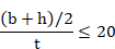
The cross section type is defined by values introduced in TSECY and TSECZ member properties (see ~MEMBPRO command). Otherwise they will be computed from the following table 10-F.5‑3:
Table 10-F.5‑3 The cross-section classification (plate thickness t < 40 mm)
|
CROSS SECTION TYPE |
Y |
Z |
|||
|
I Section
|
Rolled Section |
If
|
b |
a |
|
|
If
|
b |
b |
|
||
|
Welded Section |
b |
b |
|||
|
Channel
|
Rolled or Welded |
b |
b |
|
|
|
Pipe
|
Rolled |
a |
a |
||
|
By dimensions |
b |
b |
|||
|
L angle |
Rolled |
b |
b |
||
|
Square Tubing or Box
|
Rolled or Welded if
|
c |
c |
||
|
Standard T
|
Rolled or Welded |
b |
b |
||


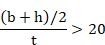

Table 10-F.5‑4 The
cross-section classification (plate thickness t  40 mm)
|
CROSS SECTION TYPE |
Y |
Z |
||
|
I Section
|
Rolled |
If
|
c |
b |
|
If
|
d |
c |
||
|
Welded (default) |
|
b |
||
|
Square Tubing or Box
|
Rolled or Welded if
|
|
b |
|
|
Rolled or Welded if
|
|
c |
||


10-F.5.4 Material Properties
In GB50017 checking, the following material properties are used:
Table 10-F.5‑5 Material properties
|
Description |
Property |
|
Steel yield strength |
|
|
Ultimate strength |
|
|
Shear strength |
|
|
Elasticity modulus |
E |


*th = plate thickness
10-F.5.5 Forces and Moments
Forces and moments for element’s ends are obtained from CivilFEM’s results file (file. RCV) for the selected load step and substep.
Table 10-F.5‑6 Forces and Moments
|
Forces and Moments |
Description |
|
|
Axial force. |
|
|
Design Shear force in Y. |
|
|
Design Shear force in Z. |
|
|
Design torsional moment. |
|
|
Bending moment in Y. |
|
|
Bending moment in Z. |


10-F.6 Checking Process
Required steps to conduct the different checks in CivilFEM are as follows:
a) Obtain the cross-section data corresponding to the element.
b) Specific section checking according to the type of external load.
c) Results. Checking results are available in CivilFEM for each element end, grouping them into alternatives in the results file .RCV, in such way that the user may access them by indicating the number of the alternative using the CivilFEM command ~CFSET.
In sections corresponding to the different types of checking, the necessary data corresponding to the each type of solicitation is described.
10-F.6.1 Bending Checking
In CivilFEM the checking of elements under bending according to GB50017 code is done for each element end of those selected elements or solid sections of the model with a cross section type of structural steel. For this check, the program follows the steps below:
10-F.6.1.1 Calculation of the Maximum Normal Stress
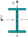
The maximum normal stress is calculated with the general equation for sections subjected to bending moments according to axes, not necessarily principal of inertia:
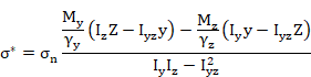
Where:
|
|
Bending moment in Y direction |
|
|
Bending moment in Z direction |
|
|
Moment of inertia in Y direction |
|
|
Moment of inertia in Z direction |
|
|
Product of inertia about YZ |


Plastic development coefficients  are obtained from the associated
member properties (see ~MEMBPRO command).
Otherwise they should be defined according to Table 10-F.6.1.
are obtained from the associated
member properties (see ~MEMBPRO command).
Otherwise they should be defined according to Table 10-F.6.1.
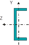
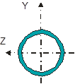
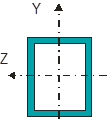
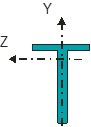
Table10-F.6.1 Plastic development coefficients
|
CROSS SECTION TYPE |
|
|
|
|
1.20 |
1.05 |
|
|
|
1.05 |
|
|
||
|
|
1.15 |
1.15 |
|
|
1.05 |
1.05 |
|
|
1.20 |
|
|
|
||
|
Otherwise |
1.00 |
1.00 |






10-F.6.1.2 Calculation of GB50017 Criterion
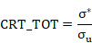
The equivalent stress previously obtained is then divided by the steel design strength su in order to obtain a value that is stored as the CRT_TOT parameter in the active alternative in CivilFEM’s results file for each element end. This value shall be between 0.0 and 1.0 so that the element will be valid according to the GB50017 code; therefore, the equivalent stress must be lower than the steel design stress.
10-F.6.2 Shear Checking
In CivilFEM, the checking of elements under shear force according to the GB50017 code is performed for each element end of those selected elements or solid sections of the model with a cross section type of structural steel.
10-F.6.2.1 Calculation of the Maximum Tangential Stress
The maximum tangential shear and torsion stresses for each element end are calculated from shear forces and section mechanical properties in the following equation:
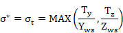
Where:
|
|
Shear Force in Y direction |
|
|
Shear Force in Z direction |
|
|
Shear area about Y axis. |
|
|
Shear area about Z axis. |


10-F.6.2.2 Calculation of GB50017 Criterion
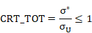
The equivalent stress obtained is divided by the steel design strength su in order to obtain a value that is stored as the CRT_TOT parameter in the active alternative in CivilFEM’s results file for each element end. This value shall be between 0.0 and 1.0 so that the element will be valid according to the GB50017 code; consequently, the equivalent stress must be lower than the steel design stress.
10-F.6.3 Bending & Shear Checking
In CivilFEM the checking of elements under bending and shear forces according to GB50017 code is done for each element end of those selected elements or solid sections of the model with a cross section type of structural steel. The following steps:
10-F.6.3.1 Calculation of the Maximum Normal Stress
The maximum normal stress is calculated with the general equation for sections subjected to bending moments according to axes, not necessarily the principal axes of inertia:

Where:
|
|
Bending moment in Y direction |
|
|
Bending moment in Z direction |
|
|
Moment of inertia in Y direction |
|
|
Moment of inertia in Z direction |
|
|
Product of inertia about YZ |
10-F.6.3.2 Calculation of the Maximum Tangential Stress
The maximum tangential shear and torsion stresses for each element end are calculated from shear forces and section mechanical properties in the following equation:
Where:
|
|
Shear Force in Y direction |
|
|
Shear Force in Z direction |
|
|
Shear area about Y axis. |
|
|
Shear area about Z axis. |
10-F.6.3.3 Calculation of the Maximum Equivalent Stress
The maximum equivalent stress in the section s* is calculated by using:
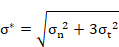
The maximum equivalent stress for each element end is stored in the active alternative in CivilFEM’s results file with the parameter named SCEQV.
10-F.6.3.4 Calculation of GB50017 Criterion
The equivalent stress obtained is divided by the steel design strength su in order to obtain a value that is stored as the CRT_TOT parameter in the active alternative in CivilFEM’s results file for each element end. This value shall be between 0.0 and 1.0 so that the element will be valid according to the GB50017 code; thus, the equivalent stress must be lower than the steel design stress.
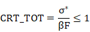
Where  is the amplifying factor for the combined
design strength. If
is the amplifying factor for the combined
design strength. If  and
and  have different sign
= 1.2, otherwise = 1.1.
have different sign
= 1.2, otherwise = 1.1.
10-F.6.4 Axial Force Checking
In CivilFEM, the checking of elements under axial forces (without considering buckling) according to the GB50017 code is done for each element end of those selected elements or solid sections of the model with a cross section type of structural steel.
10-F.6.4.1 Calculation of the Maximum Axial Stress
The maximum tangential shear and torsion stresses for each element end are calculated from shear forces and section mechanical properties in the following equation:
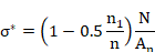
Where:
|
|
Axial force |
|
|
Net area of the cross section |
|
|
Number of high-strength frictional bolts |
|
|
Number of bolts at the calculated section |


In CivilFEM  coefficient is given by RTB factor which can be modified with ~SECMDF command.
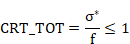
10-F.6.4.2 Calculation of GB50017 Criterion
The equivalent stress obtained is then divided by the steel design strength su in order to obtain a value that is stored as the CRT_TOT parameter in the active alternative in the CivilFEM’s results file for each element end. This value shall be between 0.0 and 1.0 so that the element will be valid according to the GB50017 code; therefore, the equivalent stress must be lower than the steel design stress.
10-F.6.5 Bending & Axial Checking
In CivilFEM, checking elements subjected to bending and axial forces according to GB50017 code is conducted for each element end of those selected elements or solid sections of the model with a cross section type of structural steel.
10-F.6.5.1 Calculation of the Maximum Equivalent Stress
The maximum equivalent stress in the section s* is calculated by using:
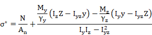
Where:
|
|
Bending moment in Y direction |
|
|
Bending moment in Z direction |
|
|
Moment of inertia in Y direction |
|
|
Moment of inertia in Z direction |
|
|
Product of inertia about YZ |
Plastic
development coefficients  are obtained from the associated member properties (see ~MEMBPRO command). Otherwise they should be defined according to Table 10-F.6.1.
10-F.6.5.2 Calculation of GB50017 Criterion
The equivalent stress obtained is then divided by the steel design strength su in order to obtain a value that is stored as the CRT_TOT parameter in the active alternative in CivilFEM’s results file for each element end. This value shall be between 0.0 and 1.0 so that the element will be valid according to the GB50017 code; therefore, the equivalent stress must be lower than the steel design stress.
10-F.6.6 Compression Buckling Checking
In CivilFEM the checking of elements considering buckling according to GB50017 code is done for each element end of those selected elements or solid sections of the model with a cross section type of structural steel and subjected to a compressive force.
10-F.6.6.1 Calculation of the Maximum Equivalent Stress
The maximum equivalent stress in the section s* is calculated by using:

Where  is the stability coefficient for axially compressed members. The stability coefficient is calculated from the slenderness ratio:


Where:
|
L |
Unbraced length of member (see ~MEMBPRO command) |
|
|
Buckling length factors in Y axis (see ~MEMBPRO command) |
|
|
Buckling length factors in Z axis (see ~MEMBPRO command) |
|
|
Rotational radius to Y axis |
|
|
Rotational radius to Z axis |


In non symmetric sections, the axes are defined as the directions of principal inertia.
To compute :
:
a) If 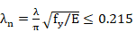 then
then 
b) Otherwise:

Where  are chosen according to the following
table:
are chosen according to the following
table:
Table 10-F.6.2 Coefficients 
|
CROSS SECTION |
|
|
|
|
|
a |
0.410 |
0.986 |
0.152 |
|
|
b |
0.650 |
0.965 |
0.300 |
|
|
c |
|
0.730 |
0.906 |
0.595 |
|
|
1.216 |
0.302 |
||
|
d |
|
1.350 |
0.868 |
0.915 |
|
|
1.375 |
0.432 |
||


The cross section type is determined from tables of chapter 10-F.5.3
10-F.6.6.2 Calculation of GB50017 Criterion
The equivalent stress obtained is then divided by the steel design strength su in order to obtain a value that is stored as the CRT_TOT parameter in the active alternative in CivilFEM’s results file for each element end. This value shall be between 0.0 and 1.0 so that the element will be valid according to the GB50017 code; consequently, the equivalent stress must be lower than the steel design stress.