

10-K.1 Scope
Steel structures checking according to ASME BPVC III Subsection NF in CivilFEM includes the checking of structures composed of welded or rolled shapes under axial forces, shear forces and bending moments in 3D.
The calculations performed by CivilFEM correspond to the provisions of this code according to the following sections:
|
1 |
Allowable Stresses |
|
2 |
Stability and Slenderness and Width-Thickness Ratios |
10-K.2 Checking Types
With CivilFEM it is possible to accomplish the following checking and analysis types:
· Checking of sections (ASME NF-3322.1) subjected to:
- Stress in Tension
- Stress in Shear
- Stress in Compression
- Stress in Bending
- Axial Compression and Bending
- Axial Tension and Bending
· Stability check (ASME NF-3322.2):
- Maximum Slenderness Ratios
- Width Ratios
10-K.3 Valid Element Types
The valid element types supported by CivilFEM are the following 2D and 3D ANSYS link and beam elements:
|
2D Link |
LINK1 |
|
3D Link |
LINK8 |
|
3D Link |
LINK10 |
|
2D Beam |
BEAM3 |
|
3D Beam |
BEAM4 |
|
3D Tapered Unsymmetrical Beam |
BEAM44 |
|
2D Tapered Elastic Unsymmetrical Beam |
BEAM54 |
|
2D Plastic Beam |
BEAM23 |
|
3D Thin-walled Beam |
BEAM24 |
|
3D Elastic Straight Pipe |
PIPE16 |
|
3D Plastic Straight Pipe |
PIPE20 |
|
3D Finite Linear Strain Beam |
BEAM188 |
|
3D Quadratic Linear Strain Beam |
BEAM189 |
Moreover, it is possible to check solid sections captured from 2D or 3D models with a transversal cross section classified as “structural steel”.
10-K.4 Valid Cross-Section Types
The valid cross-sections supported by CivilFEM for checking according to ASME BPVC III Subsection NF are the following:
- All rolled shapes included in the program libraries (see the hot rolled shapes library and ~SSECLIB command)
- The following welded beams: I shapes, U or channel shapes, T shapes, box, equal and unequal legs angles and pipes. (~SSECDMS commands).
- Structural steel sections defined by plates (command ~SSECPLT).
- Shapes from solid sections captured from 2D or 3D models which transverse cross section is classified as “structural steel” (command ~SLDSEC).
10-K.5 Calculation Basis
10-K.5.1 Section Data
The section data of the element must be included in the CivilFEM database. All geometrical and mechanical properties are automatically obtained when defining the cross section or capturing the solid section. The section data required for checking according to this code are listed below:
Table 10-I.5‑1 Section Data
|
Data |
Description |
|
A |
Area of the cross-section |
|
|
Moment of inertia about Y axis |
|
|
Moment of inertia about Z axis |
|
|
Product of inertia about YZ |
|
Y |
Coordinate Y of the considered fiber |
|
Z |
Coordinate Z of the considered fiber |
|
|
Radius of gyration about Y axis |
|
|
Radius of gyration about Z axis |
|
|
Shear area in Y |
|
|
Shear area in Z |


From the net section, only the area is considered. This area is calculated by subtracting the holes for screws, rivets and other holes from the gross sectional area. The user should be aware that the code indicates the diameter used to calculate the parameter AHOLES is greater than the real diameter (the total calculated area is introduced as the parameter AHOLES with the command ~SECMDF).
In order to determine the effective net area Ae of axially loaded tension members, the reduction coefficient Ct must be set (parameter CT with the command ~SECMDF). By default, Ct=0.75.
10-K.5.2 Member Properties
For ASME BPVC III Subsection NF, the data set checked at member level is shown in the following table. The data are stored with the section data in user units and in CivilFEM reference axis. (Parameters L, KY, KZ, CBY, CBZ, CMY, CMZ, PIN, COLUMN, BRACED of ~MEMBPRO command).
Table 10-I.5‑2 Member Properties
|
Description |
Data |
Chapter |
|
1.- Unbraced length of the member 2.- Buckling length factor in Y axis 3.- Buckling length factor in Z axis 4.- Bending coefficient dependent upon moment gradient in Y axis 5.- Bending coefficient dependent upon moment gradient in Z axis 6.- Coefficient applied to bending term in interaction equation and dependent upon column curvature caused by applied moments in Z axis 7.- Coefficient applied to bending term in interaction equation and dependent upon column curvature caused by applied moments in Y axis 8.- Pin-connected members: 0: No (default) 1: Yes 9.- Member type: 0: Beam (default) 1: Column 9.- Laterally braced in the region of compression: 0: No (default) 1: Yes |
L KY KZ CBY
CBZ
CMY
CMZ
PIN
COLUMN
BRACED |
3322 3322 3322 3322
3322
3322
3322
3322
3322
3322
|
10-K.5.3 Material Properties
The following material properties are used for checking according to ASME BPVC III Subsection NF:
Table 10-I.5‑5 Material properties
|
Description |
Property |
|
Steel yield strength |
|
|
Ultimate strength |
|
|
Modulus of Elasticity |
E |


*th = plate thickness
Furthermore, although austenitic stainless steel is an intrinsic material property, it can be modified by changing the material to User Defined.
10-K.5.4 Forces and Moments
Forces and moments for the ends of elements are obtained from CivilFEM’s results file (file. RCV) for the selected load step and substep.
Table 10-I.5‑6 Forces and Moments
|
Forces and Moments |
Description |
|
|
Axial force. |
|
|
Design Shear force in Y. |
|
|
Design Shear force in Z. |
|
|
Design torsional moment. |
|
|
Bending moment in Y. |
|
|
Bending moment in Z. |


10-K.6 Checking Process
Necessary steps to conduct the different checks in CivilFEM are as follows:
a) Obtain the cross-sectional data corresponding to the element.
b) Specific section checking according to the type of external load.
c) Results. In CivilFEM, checking results for each element end are grouped into alternatives in the results file .RCV, in such way that the user may access them by indicating the number of the alternative with the CivilFEM command ~CFSET.
The required data for the different types of checking can be found in tables within the corresponding sections in this manual.
10-K.6.1 Tension Checking
In CivilFEM, elements subjected to tension are checked according to ASME BPVC III Subsection NF code for each end of the selected elements and solid sections of the model with a structural steel cross section. The check for tension adheres to the following steps:
10-K.6.1.1 Calculation of the Allowable Stress
The allowable stress in tension shall be as given in the equations below:
Except for pin-connected and threaded members, Ft shall be:

(*)
 on the effective net area
For pin-connected members, using the net area:

10-K.6.1.2 Calculation of the Stress Criterion
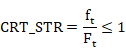
The obtained equivalent stress ft is divided by the steel design strength Ft in order to obtain a value that is stored as the CRT_STR parameter in the corresponding alternative. This value must be between 0.0 and 1.0 for the element to be valid according to the ASME BPVC III Subsection NF code; consequently, the equivalent stress must be less than the steel design strength.
10-K.6.1.3 Slenderness Ratio
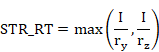
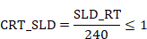
The maximum slenderness ratio l/r for tension members is obtained and stored as SLD_RT. This slenderness ratio is divided by 240 (SLD_RT shall not exceed 240) and stored as the CRT_SLD. Therefore, this value must be between 0.0 and 1.0 for the element to be valid according this code.
10-K.6.1.4 Calculation of the Total Criterion
The Total Criterion is obtained from the maximum value between the stress criterion and the slender criterion; this criterion is stored as the CRT_TOT parameter in the corresponding alternative in CivilFEM’s results file for each element end. This value must be between 0.0 and 1.0 for the element to be valid according the ASME BPVC III Subsection NF code.

10-K.6.2 Shear Checking
In CivilFEM the elements subjected to a shear force are checked according to ASME BPVC III Subsection NF code is done for each element end of those selected elements or solid sections of the model with a structural steel cross section.
10-K.6.2.1 Calculation of the Allowable Stress
The allowable stress for shear resistance of the effective section is as follows:

10-K.6.2.2 Calculation of the Total Criterion
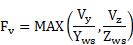
The equivalent stress obtained fV is divided by the steel design strength Fv in order to obtain a value that is stored as the CRT_TOT parameter in the active alternative in the CivilFEM’s results file for each element end. This value must be between 0.0 and 1.0 so that the element will be valid according to the ASME BPVC III Subsection NF code; consequently, the equivalent stress must be less than the steel design strength.
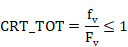
This equivalent stress fv is the maximum value obtained in both directions:
10-K.6.3 Compression Checking
In CivilFEM, elements subjected to compression are checked of according to ASME BPVC III Subsection NF for each element end of the selected elements or solid sections of the model with a structural steel cross section.
10-K.6.3.1 Calculation of the Allowable Stress
The allowable stress in compression shall be determined as described below:
1- Gross sections of columns, except those fabricated from austenitic stainless steel:
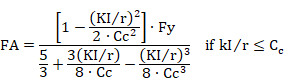
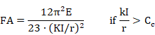
where

2- Gross sections of columns fabricated from austenitic stainless steel:
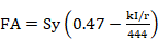 if kI/r
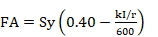 if kI/r
  120
120
3- Member elements other than columns:

10-K.6.3.2 Slenderness Ratio
The maximum slenderness ratio l/r for tension members is obtained and stored as SLD_RT. This slenderness ratio is divided by 200 (SLD_RT shall not exceed 200) and stored as the parameter CRT_SLD. Consequently, this value must be between 0.0 and 1.0 for that the element to be valid according this code.
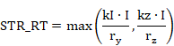
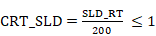
10-K.6.3.3 Stress Reduction Factor
The ASME BPVC III Subsection NF code decreases the efficiency of a section through reduction factors when axially loaded members contain elements subjected to compression and have a width-thickness ratio above the limit below:
Unstiffened Compression Elements
Unstiffened compression elements have one free edge parallel to the direction of the compressive stress. Stress on these elements shall be decreased by the reduction factor Qs when the width-thickness ratio exceeds the limits below. The flange width will be the distance from the free edge to the web.
1- For Single Angles,
when 
Qs = 1.0
when 


when b/t 155/

2- For Stems of Tees,
when 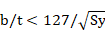

when 

when 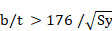

3- For other Compression Members,
when 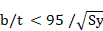
when

when
where Sy is the yield strength, in ksi.
Furthermore, proportions of unstiffened elements of channels and tees that exceed the limits above are checked for the following limits:
|
Shape |
Ratio of Flange Width to Profile Depth |
Ratio of Flange Thickness to Web or Stem Thickness |
|
Built-up Channels |
|
|
|
Rolled Channels |
|
|
|
Built-up Tees |
|
|
|
Rolled Tees |
|
|


Table NF-3322.2(e)(2)-1
This proportion checking result is defined in the CivilFEM results file (.RCV) as CTR_W with a value of 0.0 if the proportional limits are fulfilled and 2100 if they are not.
Stiffened Compression Elements
Stiffened compression elements have lateral support along both edges which are parallel to the direction of the compressive stress. If the width-thickness ratio of these elements exceeds the limit below, a reduced effective width be shall be used:
1- For the flanges of square and rectangular sections of uniform thickness:
when 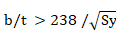
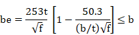
2- For other uniform compressed elements:
when 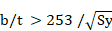
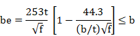
Where f is the axial compressive stress on the member based on the effective area, in ksi.
If unstiffened elements
are included in the total cross section, f must be such that the maximum
compressive stress in the unstiffened elements does not exceed  . Therefore, the calculation of the effective width of stiffened
elements adheres to the following iterative process:
. Therefore, the calculation of the effective width of stiffened
elements adheres to the following iterative process:
a) The axial compressive stress f is obtained.
b) An initial value of the effective width be is calculated.
c) A new axial compressive stress f’ of the effective area is obtained
d) If f’ exceeds FaQs, a new axial compressive stress f’’ is obtained by increasing the last axial compressive stress f’.
This process is repeated until the axial compressive stress does not exceed FaQs or until the effective area is equal to the total area.
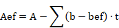
Using the effective width be, the form factor Qa is then calculated by the ratio of the effective area to the total area.

10-K.6.3.4 Calculation of the Stress Criterion
The allowable stress for axially loaded compression members shall not exceed:
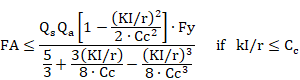
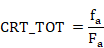
After verifing the equation above, the equivalent stress obtained fa is divided by the steel design strength Fa to obtain a value stored as the CRT_STR parameter in the active alternative in CivilFEM’s results file for each element end. This value must be between 0.0 and 1.0 so that the element will be valid according to ASME BPVC III Subsection NF; therefore, the equivalent stress must be lower than the steel design strength.
10-K.6.3.5 Calculation of the Total Criterion
The Total Criterion is obtained from the maximum value between the stress criterion and the slender criterion and is stored as the CRT_TOT parameter in the active alternative in the CivilFEM’s results file for each element end. This value must be between 0.0 and 1.0 for the element to be valid according to the ASME BPVC III Subsection NF.

10-K.6.4 Bending Checking
In CivilFEM, elements subjected bending are checked according to ASME BPVC III Subsection NF for each element end of the selected elements or solid sections of the model with a structural steel cross section.
10-K.6.4.1 Calculation of the Allowable Stress
First, the section is classified as a compact section, member with a high flange width-thickness ratio or miscellaneous member:
(a) Compact sections: For a section to qualify as compact, its flanges must be continuously connected to the web or webs and the width-thickness ratios of its compression elements must not exceed the limiting ratios below:
1- The width-thickness ratio of the compression flanges shall not exceed:
a. for unstiffened elements 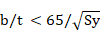
b. for stiffened elements 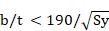
2- Depth-thickness ratio of webs
 if
if 

3-
Moreover, the compression flanges shall be
braced laterally at intervals not exceeding  nor
nor 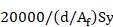 . This property is set by the user as a member property (~MEMBPRO command). If the cross section has no
compression flanges, the member will be taken into account as braced laterally.
. This property is set by the user as a member property (~MEMBPRO command). If the cross section has no
compression flanges, the member will be taken into account as braced laterally.
(b) Members with a high flange width-thickness ratio: members shall satisfy the requirements above, except unstiffened flanges shall satisfy:

(c) Miscellaneous members: limit ratios above do not apply to these members.
Next, the allowable bending stress is determined by the equations below:
1- I Sections:
a. Compact sections bent about their minor axis of inertia shall not exceed a bending stress of:

b. Members with a high flange width-thickness ratio bent about their minor axis of inertia shall not exceed a bending stress of:

c. Compact sections bent about their major axis of inertia shall not exceed:

d. Members with a high flange width-thickness ratio bent about their major axis of inertia shall not exceed a bending stress of:

e. Miscellaneous member sections bent about their major axis of inertia shall not exceed the larger value below:

when 

when 
where  is the radius of the section, comprising of the area of the
compression flange plus one-third of the area of the compression web.
is the radius of the section, comprising of the area of the
compression flange plus one-third of the area of the compression web.
When the area of the compression flange is greater than or equal to the area of the tension flange:

f. Members not included above which are braced laterally in the region of the compressive stress shall not exceed a bending stress of:

If these members are not braced laterally in the region of the compressive stress, the section will be not checked.
2- Tubular Square Box Sections:
a. Compact sections bent about their minor axis of inertia, but not necessarily braced laterally, shall not exceed a bending stress of:

b. Members not included shall not exceed a bending stress of:
However, this section strength can be decreased through reduction factors.
3- Pipe Sections:
a. If the diameter-thickness ratio of hollow, circular sections does
not exceed  , the bending stress shall not exceed:
If the diameter-thickness ratio is greater than the value above, the section will be not checked.
4- U channel Sections:
a. If the section is bent about its major axis of inertia, the bending stress shall not exceed the larger value below:

when 

when 
where is the radius of the section, comprising of the area of the
compression flange plus one-third of the area of the compression web.
When the area of the compression flange is greater than or equal to the area of the tension flange,

b. Members not included above which are braced laterally in the region of the compressive stress shall not exceed a bending stress of:
If these members are not braced laterally in the region of the compressive stress, the section will be not checked.
5- Tees Sections:
a. Compact sections loaded in the direction of the web which coincides with the minor axis of inertia, shall not exceed a bending stress of:
b. Members with a high flange width-thickness ratio which are loaded in the direction of the web coinciding with the minor axis of inertia shall not exceed a bending stress of:

c. Miscellaneous member sections loaded in the direction of the web coinciding with the minor axis of inertia, shall not exceed the larger bending stress below:
when 
When
where is the radius of a section comprising the area of the compression
flange plus one-third of the area the of compression web
When the compression flange area is greater than or equal to the tension flange area:

d. Members not included above which are braced laterally in the region of the compressive stress shall not exceed a bending stress of:
If these members are not braced laterally in the region of the compressive stress, the section will be not checked.
6- All other sections:
a. Members braced laterally in the region of the compressive stress shall not exceed a bending stress of:
If these members are not braced laterally in the region of compressive stress, the section will be not checked.
10-K.6.4.2 Stress Reduction Factor
ASME BPVC III Subsection NF Code decreases the efficiency of a section through reduction factors for flexural members containing elements subject to compression with a width-thickness ratio in excess of the limits below:
Unstiffened Compression Elements
Unstiffened compression elements have one free edge parallel to the direction of the compressive stress. When the width-thickness ratio exceeds the limits below, the stress calculation will include a reduction of factor Qs. The width of flanges is taken from distance from the free edge to the weld.
1- For Single Angles:
when 

when 

when 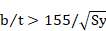

2- For Stems of Tees:
when 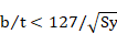
when 

when 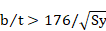

3- For Other Compression Members:
when 
when 

when
where Sy is the yield strength, in ksi.
Furthermore, unstiffened elements of channels and tees with proportions that exceed the limits above are checked for the following limits:
|
Shape |
Ratio of Flange Width to Profile Depth |
Ratio of Flange Thickness to Web or Stem Thickness |
|
Built-up channels |
|
|
|
Rolled channels |
|
|
|
Built-up tees |
|
|
|
Rolled tees |
|
|
Table NF-3322.2(e)(2)-1
This proportion checking result is written in the CivilFEM results file (.RCV) as CTR_W with a value of 0.0 if the proportion limits are satisfied and 2100 if they are not.
Stiffened Compression Elements
Stiffened compression elements have lateral support along both edges which are parallel to the direction of the compressive stress. When the width-thickness ratio of these elements exceeds the applicable limit below, a reduced effective width be shall be used:
1- For the flanges of square and rectangular sections of uniform thickness,
when 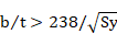
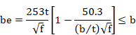
2- For other uniform compressed elements,
When 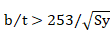
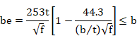
Where f is the compressive stress on member based on the effective area, in ksi.
If unstiffened elements are included in the total cross section, f must have a value such that the maximum compressive stress in the unstiffened elements does not exceed FbQs. Therefore, the calculation of the effective width of stiffened elements adheres to the following iterative process:
a) The maximum compressive stress f of the element is obtained
b) An initial value of the effective width be is calculated in all the compressive elements.
c) A new axial compressive stress f’ is obtained of the effective area.
d) If f’ exceeds FbQs, a new effective width be’ is obtained by increasing the previous effective width be.
This iteration is repeated until the axial compressive stress is less than FbQs or the effective area is equal to the total area.
Using the effective width be, the form factor Qa is then calculated by the ratio of the effective area to the total area.

10-K.6.4.3 Calculation of the Total Criterion
When reduction factors are required, the maximum allowable bending stress shall not exceed 0.6 SyQs or the Fb value as provided above.
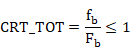
The computed bending stress fb, obtained from the effective area, is divided by the steel design strength Fb in order to obtain a value that is stored as the CRT_TOT parameter in the active alternative in CivilFEM’s results file for each element end. This value must be between 0.0 and 1.0 so that the element will be valid according to ASME BPVC III Subsection NF; therefore, the equivalent stress must be less than the steel design strength.
10-K.6.5 Axial Compression & Bending Checking
In CivilFEM the checking of elements under bending and axial compression forces according to ASME BPVC III Subsection NF code are done for each element end of those selected elements or solid sections of the model whose cross section type is structural steel.
10-K.6.5.1 Calculation of the Total Criterion
For members subjected to both axial compression and bending, stresses shall satisfy the requirements of the following equations:

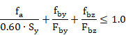
When evaluating both primary and secondary stresses:
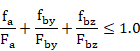
When evaluating primary stresses:
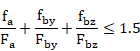
The option between primary stresses or both primary and secondary stresses can be selected through the arguments of the ~CHKSTL command.
The Total Criterion will be the maximum value of the equations below and will be stored as the CRT_TOT parameter in the active alternative in CivilFEM’s results file for each element end. This value must be between 0.0 and 1.0 for the element to be valid according to ASME BPVC III Subsection NF; therefore, the equivalent stress must be less than the steel design strength.
10-K.6.6 Axial Tension & Bending Checking
In CivilFEM, elements subjected bending and axial tension forces are checked according to ASME BPVC III Subsection NF for each element end of the selected elements or solid sections of the model with a structural steel cross section.
10-K.6.6.1 Calculation of the Total Criterion
Members subject to both axial tension and bending stresses shall satisfy the requirements of the following equation:
Where fb is the computed bending tensile stress. However, the computed bending compressive stress, taken alone, shall not exceed the allowable compressive stress Fa.
Therefore, the total criterion will be:

Where fbc is the computed bending compressive stress.
The total criterion is stored as the CRT_TOT parameter in the active alternative in CivilFEM’s results file for each element end. This value shall be between 0.0 and 1.0 for the element to be valid according to ASME BPVC III Subsection NF; consequently, the equivalent stress must be less than the steel design strength.