

Chapter 12
Prestressed Concrete Beams
12.1 Shear and Torsion according to ACI 318-05
12.1.1 Shear Checking
Shear checking according to ACI 318-05 is described in this section. These equations refer to US (British) units of force, length, and time measured in pounds, inches, and seconds.
1) Obtaining material resistant properties. The required material properties associated with each transverse cross section at the active time (see ~CFMP command) are:
 specified compressive strength of concrete.
 specified yield strength of reinforcement.
2) Obtaining geometrical data of the section. Section geometrical requirements must be defined within the CivilFEM database, (~CSECDMS commands). Required data for shear checking:
 area of concrete section.
3) Obtaining geometrical parameters depending on specified code. Geometrical parameters used for shear calculations must be defined within the CivilFEM database, (see ~SECMDF command). The required data:
 web width or diameter
of circular section, (parameter BW_VY or BW_VZ of ~SECMDF
command).
web width or diameter
of circular section, (parameter BW_VY or BW_VZ of ~SECMDF
command).
d distance from the extreme compressed fiber to the centroid of the longitudinal tensile reinforcement in the Y direction, (for circular sections, this should not be less than the distance from the extreme compressed fiber to the centroid of the tensile reinforcement in the opposite half of the member), (parameter D_Y or D_Z of ~SECMDF command).
Section “11-A.7 Previous Considerations to Shear and Torsion calculations” provides detailed information on how to calculate the required data for each code and valid section.
4) Obtaining reinforcement data of the section. Data concerning reinforcements of the section must be included within the CivilFEM database. (See ~RNFDEF and ~RNFMDF commands). Required data are the following:
a angle between shear reinforcement and the longitudinal axis of the member section, (parameter ALPHA of ~RNFDEF or ~RNFMDF commands).
 area of reinforcement per unit length (reinforcement ratio)
in both the Y and Z directions, (These can be defined directly using the ASSY
and ASSZ parameters as part of the ~RNFDEF or ~RNFMDF commands).
area of reinforcement per unit length (reinforcement ratio)
in both the Y and Z directions, (These can be defined directly using the ASSY
and ASSZ parameters as part of the ~RNFDEF or ~RNFMDF commands).
The reinforcement ratio may also be obtained with the following data:
 total area of the reinforcement legs, (parameters ASY
and ASZ of ~RNFDEF or ~RNFMDF
commands - both Y and Z directions are available).
total area of the reinforcement legs, (parameters ASY
and ASZ of ~RNFDEF or ~RNFMDF
commands - both Y and Z directions are available).
s spacing of the stirrups, (parameter S of ~RNFDEF or ~RNFMDF commands).
or with the data below:
s spacing of the stirrups, (parameter S of ~RNFDEF or ~RNFMDF commands).
f diameter of bars, (parameter PHI of ~RNFDEF or ~RNFMDF commands).
N number of reinforcement legs, (parameter N of ~RNFDEF or ~RNFMDF commands for Y and Z directions).
5) Obtaining forces and moments acting on the section. The forces and moments that act on the section are obtained from the CivilFEM results file (.RCV).
Force Description
 Factored design shear force
 Concomitant factored axial force (positive
for compression).
Concomitant factored axial force (positive
for compression).
 Concomitant factored bending moment
6) Calculating the shear strength provided by the concrete. First, the shear strength provided by the concrete (Vc) is calculated with the following expression:
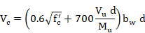
where:
 square root of specified compressive strength of
concrete, in psi (always taken as less than 100 psi).
square root of specified compressive strength of
concrete, in psi (always taken as less than 100 psi).
Such that:

Must satisfy the following:


If , despite prestressing, section is subjected to a tensile force such that the tensile stress is less than 500 psi:
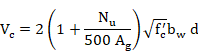
If the section
is subjected to a tensile force such that the tensile stress exceeds 500 psi,
it is assumed that  .
.
The calculated result at both element ends is stored in the CivilFEM results file as the parameter VC:
VC Shear strength provided by the concrete.

7) Calculating the shear strength provided by shear reinforcement. The shear strength provided by shear reinforcement (Vs) is calculated with the following expression:
where:
 yield strength of the shear reinforcement (not greater
than 60,000 psi).
yield strength of the shear reinforcement (not greater
than 60,000 psi).
The calculated result at both element ends is stored in the CivilFEM results file as the parameter VS:
VS Shear strength provided by transverse reinforcement.

8) Calculating the nominal shear strength of section. The nominal shear strength (Vn) is the sum of the shear strength provided by the concrete and the shear reinforcement as described in the previous sections:

This nominal shear strength, as well as its ratio to the design shear, are stored in the CivilFEM results file as the parameters:
VN Nominal shear strength.

CRTVN Ratio of the design shear force (Vu) to the resistance Vn.

If the shear strength provided by the concrete is null, and shear
reinforcement is not defined in the section, then  , and the criterion is set to –1.
9) Obtaining shear criterion. The section will be valid for shear if the following condition is satisfied

f strength reduction factor of the section, (=0.75 for shear and torsion).
Therefore, the shear checking criterion is defined as follows:
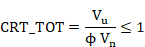
For each element, this shear utilization value is stored in the CivilFEM results file as the parameter CRT_TOT.
In cases where the shear strength provided by the concrete is null
and the shear reinforcement is not defined in the section, then , and the criterion is set equal to 2100.
The ϕ value is stored in the CivilFEM results file as the parameter VFI.
12.1.2 Torsion Checking
Torsion checking of elements according to ACI 318-05 follows the steps below:
1) Obtaining material resistant properties. These properties are obtained from the material properties associated with each transverse cross section and for the active time, (see ~CFMP command).
specified compressive strength of concrete.
specified yield strength of reinforcement.
2) Obtaining geometrical parameters depending on specified code. Geometrical parameters used for torsion calculations must be defined within the CivilFEM database, (see ~SECMDF command). The required data are the following:
web width or diameter
of circular section, (parameter BW_VY or BW_VZ of ~SECMDF command).
d distance from the extreme compression fiber to the centroid of the longitudinal tensile reinforcement in Y, (for circular sections, this must not be less than the distance from the extreme compression fiber to the centroid of the tensile reinforcement in the opposite half of the member), (parameter D_Y or D_Z of ~SECMDF command).
 Area enclosed by outside perimeter of concrete cross
section, (parameter ACP of ~SECMDF command).
Area enclosed by outside perimeter of concrete cross
section, (parameter ACP of ~SECMDF command).
 Outside perimeter of the concrete cross section, (PCP of
~SECMDF command).
Outside perimeter of the concrete cross section, (PCP of
~SECMDF command).
 Area enclosed by centerline of the outermost closed
transverse torsional reinforcement, (parameter AOH of ~SECMDF
command).
Area enclosed by centerline of the outermost closed
transverse torsional reinforcement, (parameter AOH of ~SECMDF
command).
 Perimeter of centerline of outermost closed transverse
torsional reinforcement, (parameter PH of ~SECMDF command).
Perimeter of centerline of outermost closed transverse
torsional reinforcement, (parameter PH of ~SECMDF command).
 Gross area enclosed by shear flow path, (parameter AO of
~SECMDF command).
Gross area enclosed by shear flow path, (parameter AO of
~SECMDF command).
Section “11-A.7 Previous Considerations to Shear and Torsion calculations” provides detailed information on how to calculate the required data for each valid section.
3) Obtaining reinforcement data of the section. Data concerning reinforcements of the section must be included within the CivilFEM database, (~RNFDEF and ~RNFMDF commands). Required data are the following:
Transverse Reinforcement
 area of transverse reinforcement per unit length, (this can
be defined directly using the ASST parameter as part of the ~RNFDEF
and ~RNFMDF commands).
area of transverse reinforcement per unit length, (this can
be defined directly using the ASST parameter as part of the ~RNFDEF
and ~RNFMDF commands).
The reinforcement ratio can alternatively be defined using the following data:
 closed stirrups area for torsion, (parameter AST of ~RNFDEF
and ~RNFMDF commands).
closed stirrups area for torsion, (parameter AST of ~RNFDEF
and ~RNFMDF commands).
s spacing of closed stirrups, (parameter S of ~RNFDEF and ~RNFMDF commands).
Or with the data below:
s spacing of closed stirrups, (parameter S of ~RNFDEF and ~RNFMDF commands).
 diameter of the closed stirrups, (parameter PHIT of ~RNFDEF
and ~RNFMDF commands).
diameter of the closed stirrups, (parameter PHIT of ~RNFDEF
and ~RNFMDF commands).
Longitudinal Reinforcement
 total area of the longitudinal reinforcement, (parameter
ASL of ~RNFDEF and ~RNFMDF commands).
total area of the longitudinal reinforcement, (parameter
ASL of ~RNFDEF and ~RNFMDF commands).
The reinforcement ratio can also be defined using the following data:
 diameter of longitudinal bars, (parameter PHIL of ~RNFDEF
and ~RNFMDF commands).
diameter of longitudinal bars, (parameter PHIL of ~RNFDEF
and ~RNFMDF commands).
N number of longitudinal bars, (parameter N of (~RNFDEF and ~RNFMDF commands).
4) Obtaining section internal forces and moments. The torsional moment that acts on the section is obtained from the CivilFEM results file (.RCV).
Moment Description
 Factored design torsional moment.
5) Checking whether torsion effects will be considered. Torsion effects are only considered if the design torsional moment (Tu) satisfies the following condition:
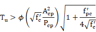
 Compressive strength in concrete (after losses) at the
section’s centroid in psi.
Compressive strength in concrete (after losses) at the
section’s centroid in psi.
If the design torsional moment is less than this value, its effects can be neglected and it is considered as null for checking.
6) Checking section dimensions. Section dimensions must satisfy the following requirements:
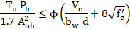
In hollow sections, if the section wall thickness is less than Aoh/Ph, this value must be replaced by the minimum thickness of the section in the expression above.
The ratio of the two coefficients is stored in the CivilFEM results file at both element ends as the parameter:
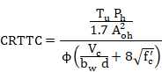
7) Calculating of the nominal torsional moment strength of the section. The nominal torsional moment strength (Tn) is evaluated by the following expression:
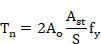
where:
specified yield strength of torsional reinforcement
(not greater than 60,000 psi).
This nominal torsional moment strength and its ratio to the design shear force are stored in the CivilFEM results file at both element ends as the parameters:
TN Nominal torsional moment strength.

CRTTN Ratio of the design torsional moment (Tu) to the torsional moment strength Tn .

The needed longitudinal reinforcement area is given by:
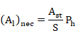
The calculated results are stored in the CivilFEM results file at both element ends as the parameters:
ALT Area of longitudinal torsional reinforcement required in accordance with the transverse torsional reinforcement defined.

CRTALT Ratio of the area of longitudinal torsional reinforcement required to the area of longitudinal torsional reinforcement defined.
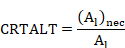
If longitudinal reinforcement is not
defined, then  , and the criterion is set equal to 2100.
8) Obtaining torsion criterion. The section will be valid for torsion if the following condition is satisfied:


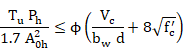
f strength reduction factor of the section, (=0.75 for shear and torsion).
Therefore, the torsion design utilization is defined as follows:
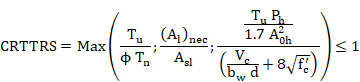
For each element end, this value is stored in the CivilFEM results file.
For cases where the torsional strength provided by the concrete is null and the torsion reinforcement is not defined in the section, the criterion will be set to 2100.
The ϕ value is stored in the CivilFEM results file for both element ends
as the parameter TFI.
value is stored in the CivilFEM results file for both element ends
as the parameter TFI.
12.1.3 Combined Shear and Torsion Checking
For checking sections subjected to shear force and associated torsional moment, the following steps are taken:
1) Checking if torsion effects must be considered. Torsion effects are only considered if the design torsional moment (Tu) satisfies the condition below:

If the design torsional moment is less than this value, its effects can be neglected and it is considered as null for checking.
2) Checking section dimensions. For shear force and associated torsional moment, section dimensions must satisfy the following requirements:
a) Solid sections:
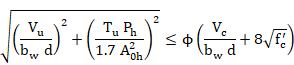
b) Hollow sections:

 In hollow sections, if the section wall thickness is lower than Aoh/Ph
, this value is replaced by the section’s minimum thickness in the
expression above.
In hollow sections, if the section wall thickness is lower than Aoh/Ph
, this value is replaced by the section’s minimum thickness in the
expression above.
The ratio between these two factors is stored in the CivilFEM results file for both element ends.
a) Solid sections:
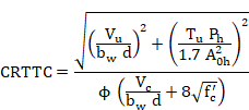
b) Hollow sections:
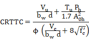
3) Checking for shear force with associated torsional moment. This check is accomplished with the same steps as for the check of elements only subjected to shear force according to ACI 318-05. The same results as defined in the shear check are calculated; except for this check, CRT_TOT criterion is stored in the CivilFEM results file as CRTSHR for each element end.
4) Checking for torsion with shear force. This checking is accomplished following the same steps considered for the checking of elements subjected only to torsion according to ACI 318-05. The same results as defined in the torsion check are calculated; except for this check, CRT_TOT criterion is stored in the CivilFEM results file as CRTTTRS for each element end.
5) Obtaining the combined shear and torsion criterion. This criterion determines whether the section is valid or not. It is defined as follows:

For each end, this value is stored in the CivilFEM results file.
A value equal to 2100 for this criterion would indicate one of the following:
h the shear strength provided by the concrete is equal to zero and shear reinforcement has not been defined.
h the shear strength provided by the concrete is equal to zero and transverse torsional reinforcement has not been defined.
h the longitudinal torsional reinforcement has not been defined.
12.1.4 Shear Design
Shear designing according to ACI 318-05 is described in this section. These equations refer to US (British) units of force, length, and time measured in pounds, inches, and seconds.
1) Obtaining material strength properties. The required material properties associated with each transverse cross section at the active time (see ~CFMP command) are:
specified compressive strength of concrete.
specified yield strength of reinforcement.
2) Obtaining geometrical data of the section. Section geometrical requirements must be defined within the CivilFEM database, (~CSECDMS command). Required data for shear design:
area of concrete section.
3) Obtaining geometrical parameters depending on code. Geometrical parameters used for shear designing must be defined within the CivilFEM database, (see ~SECMDF command). The required data:
web width or diameter
of the circular section, (parameter BW_VY or BW_VZ of ~SECMDF
command).
d distance from the extreme compressed fiber to the centroid of the longitudinal tensile reinforcement in Y, (for circular sections, this should not be less than the distance from the extreme compressed fiber to the centroid of the tensile reinforcement in the opposite half of the member), (parameter D_Y or D_Z of ~SECMDF command).
Section “11-A.7 Previous Considerations to Shear and Torsion calculations” provides detailed information on how to calculate the required data for each code and valid section.
4) Obtaining reinforcement data of the section. In shear reinforcement designing, it is possible to define the angle a between the reinforcement and the longitudinal axis of the member. This angle must be stored in the shear reinforcement data of each element, (parameter ALPHA of ~RNFDEF and ~RNFMDF commands). If this angle is equal to zero or it is not defined, a=90º. Other data concerning to reinforcements are ignored.
5) Obtaining forces and moments acting on the section. The forces and moments that act on the section are obtained from the CivilFEM results file (.RCV).
Force Description
Factored design shear force
Factored axial force occurring
simultaneously to the shear force (positive for compression).
Factored bending moment occurring
simultaneously to the shear force.
6) Calculating the shear strength provided by the concrete. First, the shear strength provided by the concrete (Vc) is calculated with the following expression:
where:
square root of specified compressive strength of
concrete, in psi (always taken as less than 100 psi).
Such as
Must satisfy the following:
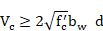

If, despite prestressing, section is subjected to a tensile force such that the tensile stress is less than 500 psi:
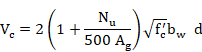
If the section
is subjected to a tensile force such that the tensile stress exceeds 500 psi,
it is assumed that .
The calculated result at both element ends is stored in the CivilFEM results file as the parameter VC:
VC Shear strength provided by the concrete.

7) Calculating the required reinforcement contribution. The section must satisfy the following condition to resist the shear force:
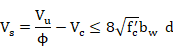
Therefore, the required shear strength of the reinforcement should be:
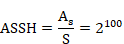
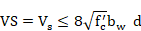
If the required shear force of the reinforcement does not satisfy the expression above, the section cannot be designed, so the parameters where the reinforcement is stored would be marked with 2100.
For this case, the element will be labeled as not designed, and the program will advance to the following element.
The calculated results are stored in the CivilFEM results file for both element ends as the parameter:
VS Shear resistance provided by the transverse reinforcement.
8) Calculating the required reinforcement ratio. Once the required shear strength of the reinforcement has been obtained, the reinforcement can be calculated with the following expression:
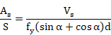
Where:
yield strength of the shear reinforcement (not greater
than 60,000 psi). (Parameter FY in ~CFMP command).
The area of the designed reinforcement per unit length is stored in the CivilFEM results file at both element ends:

In this case, the element will be labeled as designed (providing the design process is correct at both element ends).
12.1.5 Torsion Design
The design of torsional reinforcement according to ACI 318-05 follows these steps:
1) Obtaining material strength properties. These properties are obtained from the material properties associated with each transverse cross section and for the active time, (see ~CFMP command).
The required data are the following:
specified compressive strength of concrete.
specified yield strength of reinforcement.
2) Obtaining geometrical parameters depending on specified code. Geometrical parameters used for torsion designing must be defined within the CivilFEM database, (see ~SECMDF command). The required data are the following:
web width or diameter
of the circular section, (parameter BW_VY or BW_VZ of ~SECMDF
command).
d distance from the extreme compressed fiber to the centroid of the longitudinal tension reinforcement in Y, (for circular sections, this must not be less than the distance from the extreme compressed fiber to the centroid of the tension reinforcement in the opposite half of the member), (parameter D_Y or D_Z of ~SECMDF command).
Area enclosed by outside perimeter of concrete cross
section, (parameter ACP of ~SECMDF command).
Outside perimeter of the concrete cross section, (PCP of
~SECMDF command).
 Area enclosed by centerline of the outermost closed
transverse torsional reinforcement, (parameter AOH of ~SECMDF
command).
Area enclosed by centerline of the outermost closed
transverse torsional reinforcement, (parameter AOH of ~SECMDF
command).
Perimeter of centerline of outermost closed transverse
torsional reinforcement, (parameter PH of ~SECMDF command).
Gross area enclosed by shear flow path, (parameter AO of
~SECMDF command).
Section “11-A.7 Previous Considerations to Shear and Torsion calculations” provides detailed information on how to calculate the required data for each valid section.
3) Obtaining forces and moments acting on the section. The torsional moment that acts on the section is obtained from the CivilFEM results file (.RCV).
Moment Description
Design torsional moment of the l-section.
4) Checking whether torsion effects will be considered. Torsion effects are only considered if the design torsional moment (Tu) satisfies the condition below:
If the design torsional moment is less than this value, its effects can be neglected and it is considered as null for the design.
5) Checking section dimensions. Section dimensions must satisfy the following requirements:
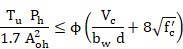
In hollow sections, if the section wall thickness is less than Aoh/Ph, the latter value must be replaced by the minimum thickness of the section in the expression above.
If the previous expression is not satisfied, the torsional reinforcement will not be designed; therefore, the parameters where the reinforcement is stored would be marked with 2100.
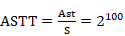 for transverse reinforcement
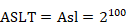 for longitudinal reinforcement
In this case, the element will be labeled as not designed and it will be stored in the TRS_NOOK component; the program will then advance to the next element.
The ratio of the two coefficients is stored in the CivilFEM results file at both element ends:
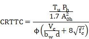
6) Calculating the required transverse reinforcement. In order to resist the torsional moment the section must satisfy the condition below:
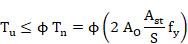
cross-sectional area of one leg of a closed stirrup
resisting torsion.
s spacing of the stirrups.
Therefore, the transverse torsion reinforcement required is:
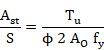
The area of the designed transverse reinforcement per unit length is stored in the CivilFEM results file for both element ends:

7) Calculating the required longitudinal reinforcement. The longitudinal reinforcement area is given by the following expression:

The area of the designed longitudinal reinforcement is stored in the CivilFEM results file for both element ends:

If both transverse and longitudinal reinforcements are designed at both element ends, this element will be labeled as designed.
12.1.6 Combined Shear and Torsion Design
The design of sections subjected to combined shear force and torsional moment follows the steps below:
1) Checking whether torsion effects will be considered. Torsion effects are only considered if the design torsional moment (Tu) satisfies the condition below:
If the design torsional moment is less than this value, its effects can be neglected and it is considered as null for designing.
2) Checking section dimensions. For shear force and associated torsional moment, section dimensions must satisfy the following requirements:
a) Solid sections:
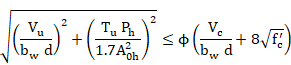
b) Hollow sections:

In hollow sections, if the section wall thickness is less than Aoh/Ph, the latter value must be replaced by the minimum thickness of the section in the formula above.
The torsion reinforcement will not be designed if the previous expression is not satisfied; as a result, the reinforcement parameters will be set as 2100. Therefore:
for transverse reinforcement
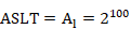 for longitudinal reinforcement
In this case, the element will be labeled as not designed, and the program will advance to the next element.
The ratio of the two coefficients is stored in the CivilFEM results file for both element ends.
a) Solid sections:
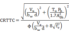
b) Hollow sections:
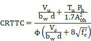
3) Shear design assuming a null torsional moment. This design follows the same procedure as for the design of elements only subjected to shear force according to ACI 318-05.
4) Torsion design considering a null shear force. This design is accomplished with the same procedure as for the design of elements subjected to pure torsion according to ACI 318-05.
12.2 Shear and Torsion according to EHE-08
12.2.1 Shear Checking
The shear checking according to EHE-08 is described in this section:
1) Obtaining material strength properties. These properties are obtained from the material properties associated with each transverse cross section and for the active time.
 characteristic compressive strength of concrete.
characteristic yield strength of reinforcement.
 mean tensile strength of concrete.
 characteristic tensile strength of concrete (fctk_005).
2) Obtaining section geometrical data. Section geometrical requirements must be defined within the CivilFEM database, (~CSECDMS commands). Required data for shear checking are the following:
 total area of the concrete section.
3) Obtaining geometrical parameters depending on specified code. Geometrical parameters used for shear calculations must be defined within the CivilFEM database, (see ~SECMDF command). Required data are the following:
minimum width of the
section in a height equal to ¾ the effective depth, (parameter BW_VY or BW_VZ
of ~SECMDF command).
d effective depth of the section, (parameter D_Y or D_Z of ~SECMDF command).
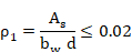
r1 geometric ratio of the longitudinal tensile reinforcement anchored at a distance greater than or equal to d from the considered section: (parameter RHO1 of ~SECMDF command):
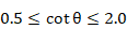
q Angle of the concrete compressive struts with the longitudinal axis of the member, (parameter THETA of ~SECMDF command):
Section “11-A.7 Previous Considerations to Shear and Torsion calculations” provides detailed information on how to calculate the required data for each code and valid section.
4) Obtaining section reinforcement data. Data concerning reinforcements of the section must be included within the CivilFEM database, (see ~RNFDEF and ~RNFMDF commands). Required data are the following:
a angle between shear reinforcement and the longitudinal axis of the member, (parameter ALPHA of ~RNFDEF or ~RNFMDF command).
area of reinforcement per unit length (reinforcement ratio)
in both the Y and Z directions, (These can be defined directly using the ASSY
and ASSZ parameters as part of the ~RNFDEF or ~RNFMDF commands).
The reinforcement ratio may also be obtained with the following data:
total area of the reinforcement legs, (parameters ASY
and ASZ of ~RNFDEF or ~RNFMDF
commands - both Y and Z directions are available).
s spacing of the stirrups, (parameter S of ~RNFDEF or ~RNFMDF commands).
or with the data below:
s spacing of the stirrups, (parameter S of ~RNFDEF or ~RNFMDF commands).
f diameter of bars, (parameter PHI of ~RNFDEF or ~RNFMDF commands).
N number of reinforcement legs, (parameter N of ~RNFDEF or ~RNFMDF command).
5) Obtaining forces and moments acting on the section. The shear force that acts on the section as well as the associated axial force and bending moment are obtained from the CivilFEM results file (.RCV).
Force Description
 Factored design shear force.
 Factored axial force occurring
simultaneously to the shear force.
Factored axial force occurring
simultaneously to the shear force.
6) Checking failure by compression in the web. First, a check is made to ensure the design shear force (Vrd) is less than or equal to the oblique compression resistance of concrete in the web (Vu1):

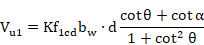
where:
 design compressive strength of concrete.

K reduction factor by axial forces effect
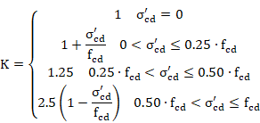
 effective axial stress in concrete (compression positive)
accounting for the axial stress taken by compressed reinforcement.
effective axial stress in concrete (compression positive)
accounting for the axial stress taken by compressed reinforcement.
For each element end, the calculated results are written in the CivilFEM results file:
VU1 Ultimate shear strength due to oblique compression of the concrete in web.

CRTVU1 Ratio of the design shear (Vrd) to the resistance Vu1.
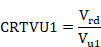
7) Checking tensile failure in the web. The design shear force (Vrd) must be less than or equal to the shear force due to tension in the web (Vu2):

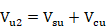
 contribution of
transverse shear reinforcement of the web to the shear strength.
contribution of
transverse shear reinforcement of the web to the shear strength.
 contribution of concrete to the shear strength.
Members Without Shear Reinforcement
If shear reinforcement has not been defined:

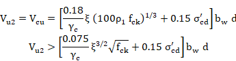
where:
 (Compression positive)
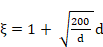 in mm
in mm
 limited to 60 MPa
Member With Shear Reinforcement
If shear reinforcement has been defined:

where:
 design strength of reinforcement (fyd
£
400 N/mm2)
design strength of reinforcement (fyd
£
400 N/mm2)
In this case, the concrete contribution to shear strength is:

where:


 reference angle of cracks inclination, obtained from:

 design normal stresses at the center of gravity of the section,
parallel to the longitudinal axis of member and to the shear force Vd
respectively (tension positive).
design normal stresses at the center of gravity of the section,
parallel to the longitudinal axis of member and to the shear force Vd
respectively (tension positive).
Taking 
In addition, the increment of tensile force due to shear force is calculated with the following equation:

For each end, calculated results are stored in the CivilFEM results file:
VSU Contribution of the shear reinforcement to the shear strength.

VCU Contribution of concrete to the shear strength.

VU2 Ultimate shear strength due to tension in the web.

CRTVU2 Ratio of the design shear force (Vrd) to the resistance Vu2 .
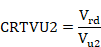
If Vu2 = 0, the CTRVU2 criterion is set as 2100.
The tension increment due to shear force is stored in the CivilFEM results file as INCTENS.
8) Obtaining shear criterion. The shear criterion indicates whether the section is valid for the design forces (if it is less than 1, the section satisfies the code provisions; whereas if it exceeds 1, the section will not be valid). Furthermore, it includes information about how close the design force is to the ultimate section strength. The shear criterion is defined as follows:
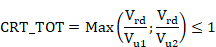
For each element end, this value is stored in the CivilFEM results file as CRT_TOT.
A value of 2100 for this criterion indicates that the shear strength due to tension in the web (Vu2) is equal to zero, as indicated in the previous step.
12.2.2 Torsion Checking
Torsion checking according to EHE-08 follows the steps below:
1) Obtaining material strength properties. These properties are obtained from the material properties associated with each transverse cross section and for the active time, (see ~CFMP command).
The required data are the following:
characteristic strength of concrete
characteristic yield strength of reinforcement
2) Obtaining geometrical parameters depending on code. Geometrical parameters used for torsion calculations must be defined within the CivilFEM database. The required data are the following:
 effective thickness, (parameter HE of ~SECMDF command).
 area involved by the centre-line of the effective hollow
section, (parameter AE of ~SECMDF command).
area involved by the centre-line of the effective hollow
section, (parameter AE of ~SECMDF command).
 perimeter of the centre-line of the effective hollow
section, (parameter UE of ~SECMDF command).
perimeter of the centre-line of the effective hollow
section, (parameter UE of ~SECMDF command).
KEYAST indicator of the position of torsional reinforcement in the section, (KEYAST parameter of ~SECMDF command):
= 0 if closed stirrups are placed in both faces of the equivalent hollow section wall or of the real hollow section (value by default for hollow sections).
= 1 if closed stirrups are only placed along the periphery of the member (value by default for solid sections).
q Angle of the compressive struts of concrete with the longitudinal axis of member, (parameter THETA of ~SECMDF command):

Section “11-A.7 Previous Considerations to Shear and Torsion calculations” provides detailed information on how to calculate the required data for each code and valid section.
3) Obtaining section reinforcement data. Data concerning reinforcements of the section must be included within the CivilFEM database, (see ~RNFDEF and ~RNFMDF commands). Required data are the following:
Transverse Reinforcement
area of transverse reinforcement per unit length, (this can
be defined directly using the ASST parameter as part of the ~RNFDEF and ~RNFMDF
commands).
The reinforcement ratio can alternatively be defined using the following data:
closed stirrups area for torsion, (parameter AST of ~RNFDEF and ~RNFMDF
commands).
s spacing of closed stirrups, (parameter S of ~RNFDEF and ~RNFMDF commands).
Or with the data below:
s spacing of closed stirrups, (parameter S of ~RNFDEF and ~RNFMDF commands).
 diameter of the closed stirrups bars, (parameter PHIT of
~RNFDEF or ~RNFMDF
command).
diameter of the closed stirrups bars, (parameter PHIT of
~RNFDEF or ~RNFMDF
command).
Longitudinal Reinforcement
total area of the longitudinal reinforcement, (parameter
ASL of ~RNFDEF and ~RNFMDF
commands).
The reinforcement ratio can also be defined using the following data:
diameter of longitudinal bars, (parameter PHIL of ~RNFDEF and ~RNFMDF
commands).
N number of longitudinal bars, (parameter N of ~RNFDEF or ~RNFMDF command).
4) Obtaining section internal forces and moments. The torsional moment that acts on the section is obtained from the CivilFEM results file (.RCV).
Moment Description
 Factored design torsional moment
5) Checking compression failure of concrete. First, a check is made to ensure the design torsional moment (Td) is less than or equal to the ultimate torsional moment by compression in concrete (Tu1); in other words, the following condition must be satisfied:

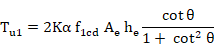
Where:
design compressive strength of concrete
K reduction factor by axial forces effect
a 0.60 if stirrups are only placed along the periphery of the member;
0.75 if closed stirrups are placed at both faces of the wall of the effective hollow section or real hollow section.
The calculated results are stored in the CivilFEM results file as:
TU1 Maximum torsional moment resisted by the section without crushing due to the compression of concrete compressive struts.

CRTTU1 Ratio of the design torsional moment (Td) to the resistance Tu1.
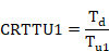
6) Checking transverse reinforcement failure. The condition of tensile failure of the transverse reinforcement of a section subjected to a torsional moment Td is:

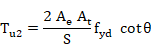
where:
design yield strength of torsional reinforcement (fyd
£
400 N/mm2).
The calculated results are stored in the CivilFEM results file as:
TU2 Maximum torsional moment that can be resisted by the section without crushing due to tension of transverse reinforcement.

CRTTU2 Ratio of the design torsional moment (Td) to the resistance Tu2.
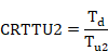
In cases where the torsion transverse reinforcement is not defined, the criterion is set as 2100.
7) Checking longitudinal reinforcement failure. The tensile failure condition of longitudinal reinforcement of a section subjected to a torsional moment Td is:

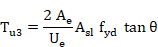
The calculated results are stored in the CivilFEM results file as:
TU3 Maximum torsional moment resisted by the section without tensile failure of the longitudinal reinforcement.

CRTTU3 Ratio of the design torsional moment (Td) to the resistance Tu3.
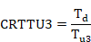
In cases where the longitudinal reinforcement is not defined, the criterion is set as 2100.
8) Obtaining torsion criterion. The torsion criterion identifies the ratio of the design moment to the section ultimate strength (if it is less than 1, the section is valid, whereas if it exceeds 1, the section is not valid). The torsion design criterion is defined as follows:

For each element end, this value is stored in the CivilFEM results file as CRT_TOT.
A value of 2100 for this criterion would indicate that one of the torsion reinforcements has not been designed.
12.2.3 Combined Shear and Torsion Checking
For checking sections subjected to shear force and associated torsional moment, we follow the steps below:
1) Torsion checking considering a null shear force. This check is accomplished with the same prodedure as for the check of elements subjected to pure torsion according to EHE-08.
Except for this check, the CRT_TOT criterion is stored in the CivilFEM results file as CRTTRS for each element end.
2) Shear checking assuming a null torsional moment. Follows the same procedure as for the checking of elements subject only to shear according to EHE-08.
Except for this check, the CRT_TOT criterion is stored in the CivilFEM results file as CRTSHR for each element end.
3) Checking the concrete ultimate strength condition by compression. The design torsional moment (Td) and the design shear force (Vrd) must satisfy the following condition:
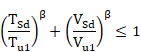
Where:
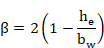
 ultimate torsional moment due to compression of concrete,
calculated in the previous chapter.
ultimate torsional moment due to compression of concrete,
calculated in the previous chapter.
 ultimate shear force by compression of concrete,
calculated in the previous chapter.
ultimate shear force by compression of concrete,
calculated in the previous chapter.
For each element, this criterion value is stored in the CivilFEM results file as CRTCST.
4) Obtaining the combined shear and torsion criterion. This criterion comprehends pure shear, pure torsion and concrete ultimate strength condition criteria. The criterion determines whether the section is valid or not, and it is defined as follows:

For each element, this criterion value is stored in the CivilFEM results file as CRT_TOT.
A value of 2100 for this criterion would indicate that one of the denominators is null, because one of the reinforcements is not defined.
12.2.4 Shear Design
The shear designing according to EHE-08 follows these steps:
1) Obtaining material strength properties. These properties are obtained from the material properties associated with each transverse cross section and for the active time, (see ~CFMP command).
characteristic strength of concrete.
characteristic yield strength of reinforcement.
mean tensile strength of concrete.
2) Obtaining geometrical data of the section. Section geometrical requirements must be defined within the CivilFEM database, (~CSECDMS command). Required data for shear designing are the following:
total area of the concrete section.
3) Obtaining geometrical parameters depending on specified code. Geometrical parameters used for shear designing must be defined within the CivilFEM database, (see ~SECMDF command). Required data are the following:
minimum width of the
section in a height equal to ¾ the effective depth, (parameter BW_VY or BW_VZ
of ~SECMDF command).
d effective depth of the section, (parameter D_Y or D_Z of ~SECMDF command).
 geometric ratio of the longitudinal tension
reinforcement anchored at a distance greater than or equal to d from the
considered section, (parameter RHO1 of ~SECMDF
command).
geometric ratio of the longitudinal tension
reinforcement anchored at a distance greater than or equal to d from the
considered section, (parameter RHO1 of ~SECMDF
command).
q angle of the concrete compressive struts to the longitudinal axis of member, (parameter THETA of ~SECMDF command):
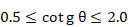
Section “11-A.7 Previous Considerations to Shear and Torsion calculations” provides detailed information on how to calculate the required data for each valid section.
4) Obtaining section reinforcement data. In shear reinforcement design, it is possible to define the angle a between the reinforcement and the longitudinal axis of the member, (parameter ALPHA of ~RNFDEF or ~RNFMDF command). If this angle is null or is not defined, it is taken as a=90º. Other reinforcement data will be ignored.
5) Obtaining forces and moments acting on the section. The shear force that acts on the section as well as the associated axial force are obtained from the CivilFEM results file (.RCV).
Force Description
Factored design shear force
Factored design axial force
6) Checking compression failure in the web. First, a check is made to ensure the design shear force (Vrd) is less than or equal to the oblique compression resistance of concrete in the web (Vu1):
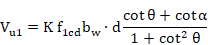
where:
design compressive strength of concrete
K reduction factor by axial forces effect
effective axial stress in the concrete (compression
positive), accounting for the axial stress taken by the reinforcement in
compression.
For each element end, the calculated results are written in the CivilFEM results file as:
VU1 Ultimate shear strength due to oblique compression of the concrete in web.
CRTVU1 Ratio of the design shear force (Vrd) to the resistance Vu1.
If the design shear force is greater than the shear force that causes failure due to the oblique compression in the web, the reinforcement design will not be feasible. Consequently, the reinforcement parameter is defined as 2100.
In this case, the element is labeled as not designed, and the program will advance to next element.
If there is no failure due to oblique compression, the calculation process continues.
7) Checking whether the section will require shear reinforcement. Firstly, a check is made to ensure the design shear force Vd is less than or equal to the shear strength provided by the concrete in members without shear reinforcement (Vcu):
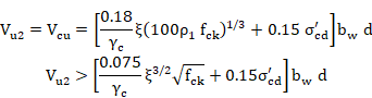
where:
 (Compression positive)
 d in mm
limited to 60 MPa
If the section does not require shear reinforcement, the following parameters are defined (at both element ends):


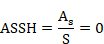
If section requires shear reinforcement the calculation process continues.
8) Determining the contribution of the required transverse reinforcement to the shear force. If the section requires shear reinforcement the validity condition for sections under shear force is the following:

contribution of shear
transverse reinforcement in the web to shear strength.
contribution of concrete to shear strength.

where:
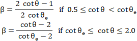
reference angle of cracks inclination, obtained from the
following expression:
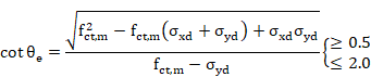
design normal stresses, at the gravity center of the section,
parallel to the longitudinal axis of the member and to the shear force Vd
respectively (tension positive)
Taking 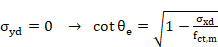
Therefore, the shear reinforcement contribution is given by the equation below:

For each element end, the value of Vcu and Vsu is stored in the CivilFEM results file:
9) Calculating the required reinforcement ratio. Once the shear force that must be carried by the shear reinforcement has been obtained, this can be calculated from the equation below:
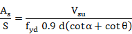
The area of designed reinforcement per unit length is stored in the CivilFEM results file for both ends:

In this case the element is marked as designed (provided that the design process is correct at both element sections).
12.2.5 Torsion Design
Torsion reinforcement design according to EHE-08 follows the following steps:
1) Obtaining material strength properties. These properties are obtained from the material properties associated with each transverse cross section and for the active time (see ~CFMP command).
characteristic strength of concrete
characteristic yield strength of
reinforcement
2) Obtaining geometrical parameters depending on specified code. Geometrical parameters used for torsion design must be defined at member level according to chapter 5 of this manual. The required data are the following:
area involved by the centre-line of the
effective hollow section, (parameter AE of ~SECMDF
command).
perimeter of the centre-line of the
effective hollow section, (parameter UE of ~SECMDF
command).
KEYAST indicator of the position of the torsion reinforcement in the section, (parameter KEYAST of ~SECMDF command).
=0 if closed stirrups are placed in both faces of the equivalent hollow section wall or of the real hollow section (value by default for hollow sections).
=1 if there are closed stirrups only along the periphery of the member (value by default for solid sections).
q angle of the concrete compressive struts with the longitudinal axis of member, (parameter THETA of ~SECMDF command):
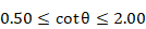
Section “11-A.7 Previous Considerations to Shear and Torsion calculations” provides detailed information on how to calculate the required data for each valid section.
3) Obtaining forces and moments acting on the section. The torsional moment that acts on the section is obtained from the CivilFEM results file (.RCV).
Moment Description
Factored design torsional moment
4) Checking compression failure of concrete. First, a check is made to ensure the design torsional moment (Td) is less than or equal to the ultimate torsional moment by compression in concrete (Tu1); in other words, the following condition must be satisfied:
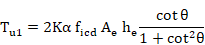
where:
f1cd concrete compressive strength

K reduction factor by axial forces effect
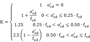
a 1.20 if stirrups are only placed along the periphery of the member.
1.50 if closed stirrups are placed at both faces of the wall of the effective hollow section or the real hollow section.
The calculated results are stored in the CivilFEM results file:
TU1 Maximum torsional moment resisted by the section without crushing due to compression of concrete compressive struts.
CRTTU1 Ratio of the design torsional moment (Td) to the resistance Tu1.
If the design torsional moment is greater than the one that causes the failure by compression of concrete, the reinforcement design is not feasible. Therefore, the parameters where these reinforcements are stored are marked as 2100.
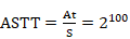 for transverse reinforcement
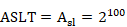 for longitudinal reinforcement
In this case, the element is labeled as not designed, and the program will advance to the next element.
If there is no failure due to oblique compression, the calculation process continues.
5) Calculating the required transverse reinforcement. The ultimate strength condition of the transverse reinforcement is:
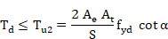
where:
 area of the section of one of the bars used as
transverse reinforcement for torsion.
area of the section of one of the bars used as
transverse reinforcement for torsion.
s spacing of the closed stirrups of the transverse reinforcement for torsion.
Therefore, the required transverse reinforcement is:
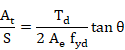
The area per unit length of the designed transverse reinforcement is stored in the CivilFEM results file for both element ends as:

6) Calculating the required longitudinal reinforcement. The ultimate strength condition of the longitudinal reinforcement is:
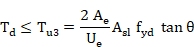
Where Asl is the area of the torsional longitudinal reinforcement.
Consequently, the longitudinal reinforcement required is:
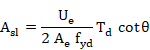
The area of the designed longitudinal reinforcement is stored in the CivilFEM results file at both element ends as:

If both element sections are designed for both transverse and longitudinal reinforcements, the element will be labeled as designed.
12.2.6 Combined Shear and Torsion Design
The design of sections subjected to shear force and associated torsional moment, follows the steps below:
1) Torsion design considering a null shear force. This design is accomplished with the same procedure as for the design of elements subjected to pure torsion according to EHE-08.
2) Shear design assuming a null torsional moment. This design follows the same procedure as for the design of elements only subjected to shear force according to EHE-08.
3) Checking compression failure condition in the concrete. The design torsional moment (Td) and the design shear force (Vrd) need to fulfill the following condition:
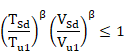
where:
ultimate torsional moment due to compression of concrete,
calculated in the previous chapter.
ultimate shear strength due to compression of concrete,
calculated in the previous chapter.
For each element end, this criterion value is stored in the CivilFEM results file as CRTCST.
4) Obtaining required shear and torsion reinforcement ratios. If the concrete ultimate strength condition is satisfied (i.e. the concrete can resist the combined shear and torsion action), the reinforcements calculated in previous chapters will be the designed reinforcements. The element will be labeled as designed.
If the ultimate strength condition of concrete is not satisfied, the reinforcement parameters will take the value of 2100.
12.3 Shear and Torsion according to EHE-98
The check and design procedure of prestressed concrete beams according to EHE-98 is the same as for non-prestressed concrete beams. This procedure is explained in Chapter 11.
12.4 Shear and Torsion according to Eurocode 2
The check and design procedure of prestressed concrete beams according to Eurocode 2 is the same as for non-prestressed concrete beams. This procedure is explained in Chapter 11.
12.5 Shear and Torsion according to ITER Design Code
The check and design procedure of prestressed concrete beams according to ITER Design Code is the same as for non-prestressed concrete beams. This procedure is explained in Chapter 11.
12.6 Shear and Torsion according to ACI 318-14
12.6.1 Shear Checking
Shear checking according to ACI 318-14 is described in this section. These equations refer to US (British) units of force, length, and time measured in pounds, inches, and seconds.
10) Obtaining material resistant properties. The required material properties associated with each transverse cross section at the active time (see ~CFMP command) are:
specified compressive strength of concrete.
specified yield strength of reinforcement.
 modification factor for lightweight concrete.
11) Obtaining geometrical data of the section. Section geometrical requirements must be defined within the CivilFEM database, (~CSECDMS commands). Required data for shear checking:
area of concrete section.
12) Obtaining geometrical parameters depending on specified code. Geometrical parameters used for shear calculations must be defined within the CivilFEM database, (see ~SECMDF command). The required data:
web width or diameter
of circular section, (parameter BW_VY or BW_VZ of ~SECMDF
command).
d distance from the extreme compressed fiber to the centroid of the longitudinal tensile reinforcement in the Y direction, (for circular sections, this should not be less than the distance from the extreme compressed fiber to the centroid of the tensile reinforcement in the opposite half of the member), (parameter D_Y or D_Z of ~SECMDF command).
Section “11-A.7 Previous Considerations to Shear and Torsion calculations” provides detailed information on how to calculate the required data for each code and valid section.
13) Obtaining reinforcement data of the section. Data concerning reinforcements of the section must be included within the CivilFEM database. (See ~RNFDEF and ~RNFMDF commands). Required data are the following:
a angle between shear reinforcement and the longitudinal axis of the member section, (parameter ALPHA of ~RNFDEF or ~RNFMDF commands).
area of reinforcement per unit length (reinforcement ratio)
in both the Y and Z directions, (These can be defined directly using the ASSY
and ASSZ parameters as part of the ~RNFDEF or ~RNFMDF commands).
The reinforcement ratio may also be obtained with the following data:
total area of the reinforcement legs, (parameters ASY
and ASZ of ~RNFDEF or ~RNFMDF
commands - both Y and Z directions are available).
s spacing of the stirrups, (parameter S of ~RNFDEF or ~RNFMDF commands).
or with the data below:
s spacing of the stirrups, (parameter S of ~RNFDEF or ~RNFMDF commands).
f diameter of bars, (parameter PHI of ~RNFDEF or ~RNFMDF commands).
N number of reinforcement legs, (parameter N of ~RNFDEF or ~RNFMDF commands for Y and Z directions).
14) Obtaining forces and moments acting on the section. The forces and moments that act on the section are obtained from the CivilFEM results file (.RCV).
Force Description
Factored design shear force
Concomitant factored axial force (positive
for compression).
Concomitant factored bending moment
15) Calculating the shear strength provided by the concrete. First, the shear strength provided by the concrete (Vc) is the least value between the following three expressions:
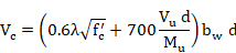

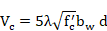
where:
square root of specified compressive strength of
concrete, in psi (always taken as less than 100 psi).
Such that:
Must satisfy the following:
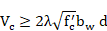
The calculated result at both element ends is stored in the CivilFEM results file as the parameter VC:
VC Shear strength provided by the concrete.
16) Calculating the shear strength provided by shear reinforcement. The shear strength provided by shear reinforcement (Vs) is calculated with the following expression:

where:
yield strength of the shear reinforcement (not greater
than 60,000 psi).
The calculated result at both element ends is stored in the CivilFEM results file as the parameter VS:
VS Shear strength provided by transverse reinforcement.
17) Calculating the nominal shear strength of section. The nominal shear strength (Vn) is the sum of the shear strength provided by the concrete and the shear reinforcement as described in the previous sections:
This nominal shear strength, as well as its ratio to the design shear, are stored in the CivilFEM results file as the parameters:
VN Nominal shear strength.
CRTVN Ratio of the design shear force (Vu) to the resistance Vn.
If the shear strength provided by the concrete is null, and shear reinforcement
is not defined in the section, then , and the criterion is set to –1.
18) Obtaining shear criterion. The section will be valid for shear if the following condition is satisfied
f strength reduction factor of the section, (=0.75 for shear and torsion).
Therefore, the shear checking criterion is defined as follows:
For each element, this shear utilization value is stored in the CivilFEM results file as the parameter CRT_TOT.
In cases where the shear strength provided by the concrete is null
and the shear reinforcement is not defined in the section, then , and the criterion is set equal to 2100.
The ϕ value is stored in the CivilFEM results file as the parameter VFI.
12.6.2 Torsion Checking
Torsion checking of elements according to ACI 318-14 follows the steps below:
9) Obtaining material resistant properties. These properties are obtained from the material properties associated with each transverse cross section and for the active time, (see ~CFMP command).
specified compressive strength of concrete.
specified yield strength of reinforcement.
modification factor for lightweight concrete.
10) Obtaining geometrical parameters depending on specified code. Geometrical parameters used for torsion calculations must be defined within the CivilFEM database, (see ~SECMDF command). The required data are the following:
web width or diameter
of circular section, (parameter BW_VY or BW_VZ of ~SECMDF
command).
d distance from the extreme compression fiber to the centroid of the longitudinal tensile reinforcement in Y, (for circular sections, this must not be less than the distance from the extreme compression fiber to the centroid of the tensile reinforcement in the opposite half of the member), (parameter D_Y or D_Z of ~SECMDF command).
Area enclosed by outside perimeter of concrete cross
section, (parameter ACP of ~SECMDF command).
Outside perimeter of the concrete cross section, (PCP of
~SECMDF command).
Area enclosed by centerline of the outermost closed
transverse torsional reinforcement, (parameter AOH of ~SECMDF
command).
Perimeter of centerline of outermost closed transverse
torsional reinforcement, (parameter PH of ~SECMDF
command).
Gross area enclosed by shear flow path, (parameter AO of
~SECMDF command).
Section “11-A.7 Previous Considerations to Shear and Torsion calculations” provides detailed information on how to calculate the required data for each valid section.
11) Obtaining reinforcement data of the section. Data concerning reinforcements of the section must be included within the CivilFEM database, (~RNFDEF and ~RNFMDF commands). Required data are the following:
Transverse Reinforcement
area of transverse reinforcement per unit length, (this can
be defined directly using the ASST parameter as part of the ~RNFDEF and ~RNFMDF
commands).
The reinforcement ratio can alternatively be defined using the following data:
closed stirrups area for torsion, (parameter AST of ~RNFDEF and ~RNFMDF
commands).
s spacing of closed stirrups, (parameter S of ~RNFDEF and ~RNFMDF commands).
Or with the data below:
s spacing of closed stirrups, (parameter S of ~RNFDEF and ~RNFMDF commands).
diameter of the closed stirrups, (parameter PHIT of ~RNFDEF and ~RNFMDF
commands).
Longitudinal Reinforcement
total area of the longitudinal reinforcement, (parameter
ASL of ~RNFDEF and ~RNFMDF
commands).
The reinforcement ratio can also be defined using the following data:
diameter of longitudinal bars, (parameter PHIL of ~RNFDEF and ~RNFMDF
commands).
N number of longitudinal bars, (parameter N of (~RNFDEF and ~RNFMDF commands).
12) Obtaining section internal forces and moments. The torsional moment that acts on the section is obtained from the CivilFEM results file (.RCV).
Moment Description
Factored design torsional moment.
13) Checking whether torsion effects will be considered. Torsion effects are only considered if the design torsional moment (Tu) satisfies the following condition:
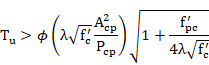
Compressive strength in concrete (after losses) at the
section’s centroid in psi.
If the design torsional moment is less than this value, its effects can be neglected and it is considered as null for checking.
14) Checking section dimensions. Section dimensions must satisfy the following requirements for solid sections:

In hollow sections:

The ratio of the two coefficients is stored in the CivilFEM results file at both element ends as the parameter (for solid sections):
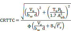
Hollow sections:
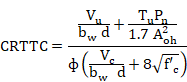
15) Calculating of the nominal torsional moment strength of the section. The nominal torsional moment strength (Tn) is evaluated by the following expression:
where:
specified yield strength of torsional reinforcement
(not greater than 60,000 psi).
This nominal torsional moment strength and its ratio to the design shear force are stored in the CivilFEM results file at both element ends as the parameters:
TN Nominal torsional moment strength.
CRTTN Ratio of the design torsional moment (Tu) to the torsional moment strength Tn .
The needed longitudinal reinforcement area is given by:
The calculated results are stored in the CivilFEM results file at both element ends as the parameters:
ALT Area of longitudinal torsional reinforcement required in accordance with the transverse torsional reinforcement defined.
CRTALT Ratio of the area of longitudinal torsional reinforcement required to the area of longitudinal torsional reinforcement defined.
If longitudinal reinforcement is not
defined, then , and the criterion is set equal to 2100.
16) Obtaining torsion criterion. The section will be valid for torsion if the following condition is satisfied:
Solid sections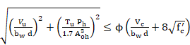
Hollow
sections 
f strength reduction factor of the section, (=0.75 for shear and torsion).
Therefore, the torsion design utilization is defined as follows:
Solid sections:
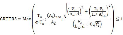
Hollow sections
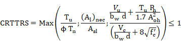
For each element end, this value is stored in the CivilFEM results file.
For cases where the torsional strength provided by the concrete is null and the torsion reinforcement is not defined in the section, the criterion will be set to 2100.
The ϕ value is stored in the CivilFEM results file for both element ends
as the parameter TFI.
12.6.3 Combined Shear and Torsion Checking
For checking sections subjected to shear force and associated torsional moment, the following steps are taken:
6) Checking if torsion effects must be considered. Torsion effects are only considered if the design torsional moment (Tu) satisfies the condition below:
If the design torsional moment is less than this value, its effects can be neglected and it is considered as null for checking.
7) Checking section dimensions. For shear force and associated torsional moment, section dimensions must satisfy the following requirements:
a) Solid sections:
b) Hollow sections:
In hollow sections, if the section wall thickness is lower than Aoh/Ph
, this value is replaced by the section’s minimum thickness in the
expression above.
The ratio between these two factors is stored in the CivilFEM results file for both element ends.
a) Solid sections:
b) Hollow sections:
8) Checking for shear force with associated torsional moment. This check is accomplished with the same steps as for the check of elements only subjected to shear force according to ACI 318-14. The same results as defined in the shear check are calculated; except for this check, CRT_TOT criterion is stored in the CivilFEM results file as CRTSHR for each element end.
9) Checking for torsion with shear force. This checking is accomplished following the same steps considered for the checking of elements subjected only to torsion according to ACI 318-14. The same results as defined in the torsion check are calculated; except for this check, CRT_TOT criterion is stored in the CivilFEM results file as CRTTTRS for each element end.
10) Obtaining the combined shear and torsion criterion. This criterion determines whether the section is valid or not. It is defined as follows:
For each end, this value is stored in the CivilFEM results file.
A value equal to 2100 for this criterion would indicate one of the following:
h the shear strength provided by the concrete is equal to zero and shear reinforcement has not been defined.
h the shear strength provided by the concrete is equal to zero and transverse torsional reinforcement has not been defined.
h the longitudinal torsional reinforcement has not been defined.
12.6.4 Shear Design
Shear designing according to ACI 318-14 is described in this section. These equations refer to US (British) units of force, length, and time measured in pounds, inches, and seconds.
1) Obtaining material strength properties. The required material properties associated with each transverse cross section at the active time (see ~CFMP command) are:
specified compressive strength of concrete.
specified yield strength of reinforcement.
modification factor for lightweight concrete.
2) Obtaining geometrical data of the section. Section geometrical requirements must be defined within the CivilFEM database, (~CSECDMS command). Required data for shear design:
area of concrete section.
3) Obtaining geometrical parameters depending on code. Geometrical parameters used for shear designing must be defined within the CivilFEM database, (see ~SECMDF command). The required data:
web width or diameter
of the circular section, (parameter BW_VY or BW_VZ of ~SECMDF
command).
d distance from the extreme compressed fiber to the centroid of the longitudinal tensile reinforcement in Y, (for circular sections, this should not be less than the distance from the extreme compressed fiber to the centroid of the tensile reinforcement in the opposite half of the member), (parameter D_Y or D_Z of ~SECMDF command).
Section “11-A.7 Previous Considerations to Shear and Torsion calculations” provides detailed information on how to calculate the required data for each code and valid section.
4) Obtaining reinforcement data of the section. In shear reinforcement designing, it is possible to define the angle a between the reinforcement and the longitudinal axis of the member. This angle must be stored in the shear reinforcement data of each element, (parameter ALPHA of ~RNFDEF and ~RNFMDF commands). If this angle is equal to zero or it is not defined, a=90º. Other data concerning to reinforcements are ignored.
5) Obtaining forces and moments acting on the section. The forces and moments that act on the section are obtained from the CivilFEM results file (.RCV).
Force Description
Factored design shear force
Factored axial force occurring
simultaneously to the shear force (positive for compression).
Factored bending moment occurring
simultaneously to the shear force.
6) Calculating the shear strength provided by the concrete. First, the shear strength provided by the concrete (Vc) is calculated as the least of the following three values:
where:
square root of specified compressive strength of
concrete, in psi (always taken as less than 100 psi).
Such as
Must satisfy the following:
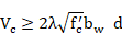
The calculated result at both element ends is stored in the CivilFEM results file as the parameter VC:
VC Shear strength provided by the concrete.
7) Calculating the required reinforcement contribution. The section must satisfy the following condition to resist the shear force:
Therefore, the required shear strength of the reinforcement should be:
If the required shear force of the reinforcement does not satisfy the expression above, the section cannot be designed, so the parameters where the reinforcement is stored would be marked with 2100.
For this case, the element will be labeled as not designed, and the program will advance to the following element.
The calculated results are stored in the CivilFEM results file for both element ends as the parameter:
VS Shear resistance provided by the transverse reinforcement.
8) Calculating the required reinforcement ratio. Once the required shear strength of the reinforcement has been obtained, the reinforcement can be calculated with the following expression:
Where:
yield strength of the shear reinforcement (not greater
than 60,000 psi). (Parameter FY in ~CFMP
command).
The area of the designed reinforcement per unit length is stored in the CivilFEM results file at both element ends:
In this case, the element will be labeled as designed (providing the design process is correct at both element ends).
12.6.5 Torsion Design
The design of torsional reinforcement according to ACI 318-14 follows these steps:
1) Obtaining material strength properties. These properties are obtained from the material properties associated with each transverse cross section and for the active time, (see ~CFMP command).
The required data are the following:
specified compressive strength of concrete.
specified yield strength of reinforcement.
2) Obtaining geometrical parameters depending on specified code. Geometrical parameters used for torsion designing must be defined within the CivilFEM database, (see ~SECMDF command). The required data are the following:
web width or diameter
of the circular section, (parameter BW_VY or BW_VZ of ~SECMDF
command).
d distance from the extreme compressed fiber to the centroid of the longitudinal tension reinforcement in Y, (for circular sections, this must not be less than the distance from the extreme compressed fiber to the centroid of the tension reinforcement in the opposite half of the member), (parameter D_Y or D_Z of ~SECMDF command).
Area enclosed by outside perimeter of concrete cross
section, (parameter ACP of ~SECMDF command).
Outside perimeter of the concrete cross section, (PCP of
~SECMDF command).
Area enclosed by centerline of the outermost closed
transverse torsional reinforcement, (parameter AOH of ~SECMDF
command).
Perimeter of centerline of outermost closed transverse
torsional reinforcement, (parameter PH of ~SECMDF
command).
Gross area enclosed by shear flow path, (parameter AO of
~SECMDF command).
Section “11-A.7 Previous Considerations to Shear and Torsion calculations” provides detailed information on how to calculate the required data for each valid section.
3) Obtaining forces and moments acting on the section. The torsional moment that acts on the section is obtained from the CivilFEM results file (.RCV).
Moment Description
Design torsional moment of the l-section.
4) Checking whether torsion effects will be considered. Torsion effects are only considered if the design torsional moment (Tu) satisfies the condition below:
If the design torsional moment is less than this value, its effects can be neglected and it is considered as null for the design.
5) Checking section dimensions. Section dimensions must satisfy the following requirements solid sections:
In hollow sections:
In hollow sections, if the section wall thickness is less than Aoh/Ph, the latter value must be replaced by the minimum thickness of the section in the expression above.
If the previous expression is not satisfied, the torsional reinforcement will not be designed; therefore, the parameters where the reinforcement is stored would be marked with 2100.
for transverse reinforcement
for longitudinal reinforcement
In this case, the element will be labeled as not designed and it will be stored in the TRS_NOOK component; the program will then advance to the next element.
The ratio of the two coefficients is stored in the CivilFEM results file at both element ends:
a) Solid sections:
b) Hollow sections:
6) Calculating the required transverse reinforcement. In order to resist the torsional moment the section must satisfy the condition below:
cross-sectional area of one leg of a closed stirrup
resisting torsion.
s spacing of the stirrups.
Therefore, the transverse torsion reinforcement required is:
The area of the designed transverse reinforcement per unit length is stored in the CivilFEM results file for both element ends:
7) Calculating the required longitudinal reinforcement. The longitudinal reinforcement area is given by the following expression:
The area of the designed longitudinal reinforcement is stored in the CivilFEM results file for both element ends:
If both transverse and longitudinal reinforcements are designed at both element ends, this element will be labeled as designed.
12.6.6 Combined Shear and Torsion Design
The design of sections subjected to combined shear force and torsional moment follows the steps below:
1) Checking whether torsion effects will be considered. Torsion effects are only considered if the design torsional moment (Tu) satisfies the condition below:
If the design torsional moment is less than this value, its effects can be neglected and it is considered as null for designing.
2) Checking section dimensions. For shear force and associated torsional moment, section dimensions must satisfy the following requirements:
a) Solid sections:
b) Hollow sections:
In hollow sections, if the section wall thickness is less than Aoh/Ph, the latter value must be replaced by the minimum thickness of the section in the formula above.
The torsion reinforcement will not be designed if the previous expression is not satisfied; as a result, the reinforcement parameters will be set as 2100. Therefore:
for transverse reinforcement
for longitudinal reinforcement
In this case, the element will be labeled as not designed, and the program will advance to the next element.
The ratio of the two coefficients is stored in the CivilFEM results file for both element ends.
a) Solid sections:
b) Hollow sections:
3) Shear design assuming a null torsional moment. This design follows the same procedure as for the design of elements only subjected to shear force according to ACI 318-14.
4) Torsion design considering a null shear force. This design is accomplished with the same procedure as for the design of elements subjected to pure torsion according to ACI 318-14.