

- CivilFEM Documentation
- CivilFEM Commands Reference
- A commands
- B commands
- ~BLCBDEL
- ~BLCBEND
- ~BLCBLD
- ~BLCBPA
- ~BLCBST
- ~BLF2CMB
- ~BLFDEL
- ~BLFDF
- ~BLFLST
- ~BLPL
- ~BLPLPL
- ~BLSA
- ~BLSB
- ~BLSEND
- ~BLSOLVE
- ~BLSST
- ~BLSTF
- ~BLVA
- ~BLVB
- ~BLVC
- ~BLVD
- ~BLVDEL
- ~BLVEND
- ~BLVGEN
- ~BLVLIB
- ~BLVLST
- ~BLVMDF
- ~BLVR
- ~BLVST
- ~BLWRITE
- ~BMSHDEL
- ~BMSHGEN
- ~BMSHLST
- ~BMSHOFF
- ~BMSHPRO
- ~BRAC
- ~BRADDEL
- ~BRADDPL
- ~BRANG
- ~BRBC
- ~BRCS
- ~BRCSOPT
- ~BRDEF
- ~BRDELEL
- ~BRDELPL
- ~BRGEN
- ~BRHL
- ~BRHLDEL
- ~BRHLMDF
- ~BRINIP
- ~BRIQR
- ~BRMVDL
- ~BRPD
- ~BRPLST
- ~BRSBOX
- ~BRSCN
- ~BRSDEL
- ~BRSDIV
- ~BRSGEN
- ~BRSKTCH
- ~BRSLST
- ~BRSMDF
- ~BRSSLAB
- ~BRSTOCS
- C commands
- ~CALSERC
- ~CBDMS
- ~CFABOUT
- ~CFACTIV
- ~CFCLEAR
- ~CFCONFG
- ~CFEXIT
- ~CFFILE2
- ~CFFL3D
- ~CFGET
- ~CFHBRD
- ~CFHBWR
- ~CFLSSLV
- ~CFLSWRT
- ~CFMP
- ~CFMPDEL
- ~CFMPGEN
- ~CFMPLIB
- ~CFMPLST
- ~CFRAPPN
- ~CFRESUM
- ~CFSAVE
- ~CFSET
- ~CFVGET
- ~CFVLEN
- ~CFVMASK
- ~CHKCON
- ~CHKPRS
- ~CHKSTL
- ~CLPRD
- ~CMB
- ~CMBCLR
- ~CMBDAT
- ~CMBDEF
- ~CMBDEL
- ~CMBINQ
- ~CMBLST
- ~CMBMOD
- ~CMBPRM
- ~CMBSTAT
- ~CODESEL
- ~COMBINE
- ~COST
- ~COSTLST
- ~CPDEF
- ~CPSTDEF
- ~CRLTCOM
- ~CRLTDEF
- ~CRLTDEL
- ~CRLTLST
- ~CRLTUSE
- ~CSDEL
- ~CSECDMS
- ~CSGEN
- ~CSIQR
- ~CSLIB
- ~CSLST
- ~CSMRG
- D commands
- E commands
- F commands
- G commands
- H commands
- I commands
- L commands
- M commands
- P commands
- ~P_SPEC
- ~PCCBDEL
- ~PCCBEND
- ~PCCBPA
- ~PCCBST
- ~PCCTMDF
- ~PCDEL
- ~PCEPDEL
- ~PCEPDEF
- ~PCEPGEN
- ~PCEPMDF
- ~PCLOSS
- ~PCPL
- ~PCPLPL
- ~PCPPDEL
- ~PCPPDEF
- ~PCPPGEN
- ~PCPPMDF
- ~PCTNDEL
- ~PCTNDEF
- ~PCTNGEN
- ~PCTNLST
- ~PCTNMDF
- ~PCTYPE
- ~PL2DINT
- ~PL2DPRS
- ~PLCSBS
- ~PLCSCON
- ~PLCSEC3
- ~PLCSSTR
- ~PLFILE
- ~PLHBMAT
- ~PLHCLPF
- ~PLLSCON
- ~PLLSFOR
- ~PLLSPRS
- ~PLLSSTL
- ~PLLSSTR
- ~PLSEEP
- ~PLSHCLP
- ~PLSHCON
- ~PLSHFOR
- ~PLSHPRS
- ~PLSHSTR
- ~PLTEND
- ~PR2DINT
- ~PR2DPRS
- ~PRCON
- ~PRFOR
- ~PRHCLPF
- ~PRPRS
- ~PRSHCLP
- ~PRSTL
- ~PRSTR
- ~PUSHDEF
- ~PUSHLST
- ~PUSHMOD
- ~PUSHSLV
- R commands
- S commands
- ~SBBMDEF
- ~SBCANNT
- ~SBCLEAR
- ~SBLST
- ~SBPAR
- ~/SBSHOW
- ~SBSMDEF
- ~SBSMMDF
- ~SD2SH
- ~SEC2DIN
- ~SEC2DOU
- ~SECMDF
- ~SEEPAGE
- ~SEEPMOD
- ~SHLDEL
- ~SHLGEN
- ~SHLIPSH
- ~SHLLST
- ~SHLMDF
- ~SHLRNF
- ~SHLSHR
- ~SHLSTL
- ~SLDDEL
- ~SLDLST
- ~SLDMDF
- ~SLDSEC
- ~SLPCIR
- ~SLPCIRK
- ~SLPIN
- ~SLPINK
- ~SLPLST
- ~SLPOPT
- ~SLPPOL
- ~SLPPWP
- ~SLPSOL
- ~SLPTAN
- ~SLPTANK
- ~SSECDMS
- ~SSECLIB
- ~SSECPLT
- ~STSTCFT
- ~STSTDEF
- T commands
- U commands
- V commands
- W commands
- 6.1 CivilFEM Combinations
- 6.2 Results Combination in ANSYS and in CivilFEM
- 6.3 Basic Terminology
- 6.4 Types of Combination Rules
- 6.5 Data Groups
- 6.6 Envelopes
- 6.7 Concomitance at Load and Model Level
- 6.8 Comment about Beam188 and Beam189 Elements
- 6.9 Start State Combinations with Prestressing Tendons
- 6.10 Calculation of All Possible Load Cases
- 6.11 Automatic Load Combinations for Standards
- 11–A.1 Introduction
- 11–A.2 Predesign of Rectangular Sections
- 11–A.3 3D Interaction Diagram
- 11–A.4 Axial Load and Biaxial Bending Checking
- 11–A.5 Axial Load and Biaxial Bending Design (Reinforcement Factor)
- 11–A.6 Axial Load and Biaxial Bending Design (Reinforcement Amount)
- 11–A.7 Calculation Codes
- 11–A.8 Previous Considerations to Shear and Torsion Calculation
- 11–A.9 Shear and Torsion according to Eurocode 2 (ENV 1992–1–1:1991)
- 11–A.10 Shear and Torsion according to Eurocode 2 (EN 1992–1–1:2004/AC:2008) and ITER Design Code
- 11–A.11 Shear and Torsion according to ACI 318–05
- 11–A.12 Shear and Torsion according to ACI 318–14
- 11–A.13 Shear and Torsion according to ACI 318–19
- 11–B.1 Introduction
- 11–B.2 Shear and Torsion according to EHE–98
- 11–B.3 Shear and Torsion according to EHE–08
- 11–B.4 Shear and Torsion according to BS8110
- 11–B.5 Shear and Torsion according to AS3600
- 11–B.6 Shear and Torsion according to GB50010–2002
- 11–B.7 Shear and Torsion according to GB50010–2010
- 11–B.8 Shear and Torsion according to NBR6118
- 11–B.9 Shear and Torsion according to AASHTO Standard Specifications for Highway Bridges
- 11–B.10 Shear and Torsion according to Code of Rules 52–101–03 and SP 63.13330.2012
- 11–B.11 Shear and Torsion according to IS 456
- 11–C.1 Introduction
- 11–C.2 Shear and Torsion according to ACI 349–01 y ACI 349–06
- 11–C.3 Shear and Torsion according to ACI 349–13
- 11–C.4 Cracking Analysis
- 11–C.5 Cracking Checking according Eurocode 2 (ENV 1992–1–1:1991)
- 11–C.6 Cracking Checking according Eurocode 2 (EN 1992–1–1:2004/AC:2008) and ITER Design Code
- 11–C.7 Cracking Checking according to ACI 318–05 and ACI 318–14
- 11–C.8 Cracking Checking according to EHE (EHE–98 and EHE–08)
- 13.1 General Concepts
- 13.2 Design for Bending Moment and Torsion – Wood–Armer Method
- 13.3 Design under Bending Moment and In Plane Loading – CEB–FIP Method
- 13.4 Design according to the Orthogonal Directions Method
- 13.5 Design according to the Most Unfavorable Direction Method
- 13.6 Check and Design for Out–of–Plane Shear Loadings according to Eurocode 2 (ENV 1992–1–1:1991)
- 13.7 Check and Design for Out–of–Plane Shear Loadings according to Eurocode 2 (EN 1992–1–1:2004/AC:2008) and ITER Design Code
- 13.8 Check and Design for Out–of–Plane Shear Loadings according to EHE–98
- 13.9 Check and Design for Out–of–Plane Shear Loadings according to EHE–08
- 13.10 Check and Design for Out–of–Plane Shear Loadings according to Code of Rules 52–101–03 and SP 63.13330.2012
- 13.11 Check and Design for Out–of–Plane Shear Loadings according to ACI 318–05
- 13.12 Check and Design for Out–of–Plane Shear Loadings according to ACI 318–14
- 13.13 Check and Design for Out–of–Plane Shear Loadings according to ACI 318–19
- 13.14 Check and Design for Out–of–Plane Shear Loadings according to ACI 349–01 and ACI 349–06 (Reinforced Concrete)
- 13.15 Check and Design for Out–of–Plane Shear Loadings according to ACI 349–13 (Reinforced Concrete)
- 13.16 Check and Design for In–plane Shear Loadings according to ACI 349–01and ACI 349–06
- 13.17 Check and Design for In–plane Shear Loadings according to ACI 349–13
- 13.18 Check and Design according to ACI 359–04 (Reinforced Concrete)
- 13.19 Check and Design according to ACI 359–04 (Prestressed Concrete)
- 13.20 Cracking Checking according Eurocode 2 (EN 1992–1–1:2004/AC:2008)
- 13.21 Cracking Checking according to ACI 318–05, ACI 318–14 and ACI 318–19
- 13.22 Cracking Checking according to Code of Rules 52–101–03 and SP 63.13330.2012
- 14.1 Introduction
- 14.2 Spectrum Calculation according to Eurocode 8 (ENV–1998–1–1:1994)
- 14.3 Spectrum Calculation according to Eurocode 8 (EN–1998–1:2004)
- 14.4 Spectrum Calculation according to NCSE–94
- 14.5 Spectrum Calculation according to NCSE–02
- 14.6 Spectrum Calculation according to GB50011
- 14.7 Spectrum Calculation according to GB50011–2010
- 14.8 Spectrum Calculation according to IT3274
- 14.9 Spectrum Calculation according to AASHTO LRFD Bridge Design Specifications
- 14.10 Spectrum Calculation according to EAK 2000
- 14.11 Spectrum Calculation according to CALTRANS Seismic Design Criteria
- 14.12 Spectrum Calculation according to the Uniform Building Code (1997)
- 14.13 Spectrum Calculation according to PS 92
- 14.14 Spectrum Calculation according to the Indian Standard 1893
- 14.15 Modal Analysis of the Structure
- 14.16 Modes Combination
- 14.17 Push Over Analysis
- 14.18 Seismic Safety Margin
- 17–A.1 Introduction
- 17–A.2 Definition of Layered Soils
- 17–A.3 Ballast Module
- 17–A.4 Retaining Walls 1 ½ D
- 17–A.5 Slope Stability
- 17–A.6 Mohr–Coulomb Plasticity Model
- 17–A.7 Cam–Clay Plasticity Model
- 17–A.8 Hoek and Brown's Failure Criteria
- 17–A.9 Seepage
- 17–A.10 Earth Pressures
- 17–A.11 Terrain Initial Stress
- /SBSHOW
- ACTMAT
- ACTTIME
- ALTER
- BLCBDEL
- BLCBEND
- BLCBLD
- BLCBPA
- BLCBST
- BLF2CMB
- BLFDEL
- BLFDF
- BLFLST
- BLPL
- BLPLPL
- BLSA
- BLSB
- BLSEND
- BLSOLVE
- BLSST
- BLSTF
- BLVA
- BLVB
- BLVC
- BLVD
- BLVDEL
- BLVEND
- BLVGEN
- BLVLIB
- BLVLST
- BLV;DF
- BLVR
- BLVST
- BLWRITE
- BMSHDEL
- BMSHGEN
- BMSHLST
- BMSHOFF
- BMSHPRO
- BRAC
- BRADDEL
- BRADDPL
- BRANG
- BRBC
- BRCS
- BRCSOPT
- BRDEF
- BRDELEL
- BRDELPL
- BRGEN
- BRHL
- BRHLDEL
- BRHLMDF
- BRINIP
- BRIQR
- BRMVDL
- BRPD
- BRPLST
- BRSCN
- BRSDEL
- BRSDIV
- BRSGEN
- BRSKTCH
- BRSBOX
- BRSLST
- BRSMDF
- BRSSLAB
- BRSTOCS
- CALSERC
- CBDMS
- CFABOUT
- CFACTIV
- CFCLEAR
- CFCONFG
- CFEXIT
- CFFILE2
- CFFL3D
- CFGET
- CFHBRD
- CFHBWR
- CFLSSLV
- CFLSWRT
- CFMP
- CFMPDEL
- CFMPGEN
- CFMPLIB
- CFMPLST
- CFRAPPN
- CFRESUM
- CFSAVE
- CFSET
- CFVGET
- CFVLEN
- CFVMASK
- CHKCON
- CHKPRS
- CHKSTL
- CLPRD
- CMB
- CMBCLR
- CMBDAT
- CMBDEF
- CMBDEL
- CMBINQ
- CMBLST
- CMBMOD
- CMBPRM
- CMBSTAT
- CODESEL
- COMBINE
- COST
- COSTLST
- CPDEF
- CPSTDEF
- CRLTCOM
- CRLTDEF
- CRLTDEL
- CRLTLST
- CRLTUSE
- CSDEL
- CSECDMS
- CSGEN
- CSIQR
- CSLIB
- CSLST
- CSMRG
- DAHEAD
- DASEEP
- DEFSPEC
- DIMCON
- DIMPRS
- DIMPRS
- DIMSTL
- DLHEAD
- DLSEEP
- EFFPRES
- EFSAPPL
- EFSCALC
- EFSLST
- ENVDEF
- ENVDEL
- ENVELOP
- ETHSF
- ETHSFE
- FL3DRES
- FMREAD
- FMWRITE
- FRMBS
- FRMCPY
- FRMCR
- FRMDEF
- FRMDEL
- FRMGEN
- FRMGT
- FRMLDS
- FRMLST
- FRMMDL
- FRMVHS
- FRTRCK
- GENSPEC
- GENTEN
- GRCSBS
- GRCSCON
- GRCSEC3
- GRCSSTR
- GRSLPD
- GRSLPR
- GTPD
- HBSOLVE
- HCLPFCN
- HCLPFST
- IDHCLPF
- ILCLOSE
- ILOPEN
- ISOBAR
- L_MOD
- L_SPEC
- LINCMB
- LINLST
- LPRNSOL
- LPSOLVE
- LSTFMT
- MEMBDEL
- MEMBGEN
- MEMBLST
- MEMBPRO
- MOD_SF
- MODLSOL
- P_SPEC
- PCCBDEL
- PCCBEND
- PCCBPA
- PCCBST
- PCCTMDF
- PCDEL
- PCEPDEF
- PCEPDEL
- PCEPGEN
- PCEPMDF
- PCLOSS
- PCPL
- PCPLPL
- PCPPDEF
- PCPPDEL
- PCPPGEN
- PCPPMDF
- PCTNDEF
- PCTNDEL
- PCTNGEN
- PCTNLST
- PCTNMDF
- PCTYPE
- PL2DINT
- PL2DPRS
- PLCSBS
- PLCSCON
- PLCSEC3
- PLCSSTR
- PLFILE
- PLHBMAT
- PLHCLPF
- PLLSCON
- PLLSFOR
- PLLSPRS
- PLLSSTL
- PLLSSTR
- PLSEEP
- PLSHCLP
- PLSHCON
- PLSHFOR
- PLSHPRS
- PLSHSTR
- PLSHPRS
- PLTEND
- PR2DINT
- PR2DPRS
- PRCON
- PRFOR
- PRHCLPF
- PRPRS
- PRSHCLP
- PRSTL
- PRSTR
- PUSHDEF
- PUSHLST
- PUSHMOD
- PUSHSLV
- RCVWRT
- REDEF
- REDEL
- RETROFT
- RNFDEF
- RNFMDF
- SBBMDEF
- SBCANNT
- SBCLEAR
- SBLST
- SBPAR
- SBSMDEF
- SBSMMDF
- SD2SH
- SEC2DIN
- SEC2DOU
- SECMDF
- SEEPAGE
- SEEPMOD
- SHLDEL
- SHLGEN
- SHLIPSH
- SHLLST
- SHLMDF
- SHLRNF
- SHLSHR
- SHLSTL
- SLDDEL
- SLDLST
- SLDMDF
- SLDSEC
- SLPCIR
- SLPCIRK
- SLPIN
- SLPINK
- SLPLST
- SLPOPT
- SLPPOL
- SLPPWP
- SLPSOL
- SLPTAN
- SLPTANK
- SSECDMS
- SSECLIB
- SSECPLT
- STSTCFT
- STSTDEF
- TENLD
- TERDEF
- TERDEL
- TERGEN
- TERLST
- TETHEX
- TIS
- TN2DIN
- TNADDEL
- TNADDPL
- TNADV
- TNGEN
- TNINIP
- TNSKTCH
- TPLST
- TPHASE
- TPOST
- TPSET
- TREFINE
- TRGDEF
- TRGDEL
- TRGLST
- TRGUPT
- TSOLVE
- TSTEP
- TTRUSS
- UNITS
- UPDATE
- VARTH
- VERIF
- VWHTML
- VWTXT
- VWXLS
- WALLANC
- WALLGEN
- WALLINI
- WALLJNT
- WALLMOD
- WALLSOL
- WALLSTP
- WATTAB
- WEIGHT
- WTSLP
- WTSOLVE
Chapter
15
Exporting Utilities
15.1 Exportation and Graphical Representation of Arrays in Microsoft Excel
The array exportation utility automatically creates a Microsoft Excel workbook with data generated by ANSYS and CivilFEM that can be used to further process the data as well as to organize the data for improved comprehension and interpretation.
The workbook includes two sheets:
· In the CivilFEM Data sheet, exported arrays are stored in columns. The header of each vector is the name utilized in ANSYS.
· In the CivilFEM Graphic sheet, arrays are represented in an Excel XY graphic according to options selected by the user.
Numerical arrays of any length can be exported and may be created with any ANSYS or CivilFEM command. This workbook is attained by applying the ~VWXLS command.
This utility is compatible with Excel 97, Excel 2000 and Excel XP versions.
15.2 Export Arrays to HTML or ASCII
As with an EXCEL worksheet, arrays can be exported to create an HTML or ASCII plane text document with a table composed of the selected arrays.
The table header will include the name of the arrays.
Numerical arrays of any length can be exported and may be created with any ANSYS or CivilFEM command. The ~VWHTML command is used to generate the HTML document and the ~VWTXT command is used for the ASCII plain text document.
The HTML code generated is standard HTML 4.0.
15.3 Import from Revit
Definition: Through Revit, this utility generates macros in APDL to import steel structure models from Revit into CivilFEM.
Using the Application Programming Interface (API) within Revit Structure, the user can obtain properties from the Revit models; these properties include the analytical geometry (position of the nodes and elements) as well as the section and material properties.
15.3.1 Sections
Revit contains a catalogue of steel sections that can be used throughout the program. Sections created in CivilFEM are created by type and dimensions.
The program considers the family names of sections utilized in Spain, France and the United States.
The element type used is Beam 188.
15.3.2 Steel
The program imports the steel with the discretization of the yield strength. This value should not differ more than 5% with the steel defined in CivilFEM when compared to the same type of steel, European or American.
15.3.4 Exportation
The exportation of the model can be performed through the Revit Structure graphical interface.

The following window will appear:
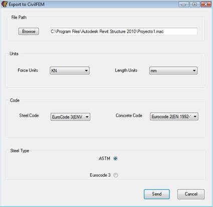
1. Select the File Path: The file path which contains the Revit Project will appear in the window. If the project has not been saved, the file path of the Revit Structure 2010 Program will appear. The user may edit this window to select the appropriate path. The file .mac will have the same name as the project.
2. Select the Units: Using the options provided, select the length and force units of the CivilFEM model. Default units will be those utilized in the Revit model.
3. Select the Code: The user may choose structural codes to check and design within CivilFEM. Eurocodes will be the default codes.
4. Select Steel Type: The user can also choose the type of steel used within CivilFEM; by default, ASTM steel will be used.