

~CFGET
~CFGET, Par, Entity, ENTNUM, Lab1, Lab2, Lab3, IDX1, IDX2, IDX3
Obtains values from the CivilFEM database and stores them in a user defined parameter
DATABASE: Parameter
Par
The name of the resulting parameter.
Entity
Entity keyword. Valid keywords are shown in the table below.
|
ACTIVE |
CivilFEM general data |
|
MATERIAL |
Material properties |
|
SECTION |
Cross sections properties |
|
SHLVERT |
Shell vertices properties |
|
MEMBPROP |
Code member properties |
|
BMSHPROP |
Beam or shell properties |
|
SLDSEC |
Solid sections properties |
|
ELEMENT |
Solution at element and section level |
|
SOLID |
Solution at solid section level |
|
SLOPE |
Properties related to slope stability |
|
FOUNDAT |
Properties related to foundation |
|
TERRAIN |
Properties related to terrain |
|
WALL |
Properties related to retaining walls |
|
BRIDGE |
Properties related to the bridges module |
|
PRSCONC |
Properties related to the prestressed module |
|
FRAME |
Properties related to predesigned frames |
|
SEISM |
Properties related to seismic analysis |
ENTNUM
Entity number. Valid values are the ones described in the tables below.
Lab1
Name of a particular item for the given entity. Valid values for each entity are the ones described in the columns of the following tables referred to Lab1.
Lab2, Lab3
Additional sets of item labels to further qualify the item for which data are to be retrieved. Valid values for each Lab1 are described in the following tables. Most parameters do not need a value of Lab3.
IDX1, IDX2, IDX3
Numbers identifying the data defined in Lab1, Lab2 and Lab3. Most data do not need that level of information.
Most of the parameters are stored in the CivilFEM database and can be recovered at any given moment. The different properties are grouped according to the entities to which they belong (ENTNUM) in the following order:
· ~CFGET - CONFIG
· ~CFGET - ACTIVE
· ~CFGET - MATERIAL
· ~CFGET - SECTION
· ~CFGET - SHLVERT
· ~CFGET - MEMBPROP
· ~CFGET - BMSHPROP
· ~CFGET - SLDSEC
· ~CFGET - ELEMENT
· ~CFGET - SOLID
· ~CFGET - SLOPE
· ~CFGET - FOUNDAT
· ~CFGET - TERRAIN
· ~CFGET - WALL
· ~CFGET - BRIDGE
· ~CFGET - PRSCONC
· ~CFGET - FRAME
· ~CFGET - SEISM
· ~CFGET – CONFIG (ENTNUM = 0 or blank)
~CFGET, Par, CONFIG, 0, Lab1, Lab2, Lab3, IDX1, IDX2, IDX3
Lab1= AS3600
~CFGET, Par, CONFIG, 0, AS3600, Lab2, , IDX1, IDX2, IDX3
Retrieves configuration data for the Australian AS3600 code. Valid labels are:
|
Lab2 |
Description |
|
PHI |
Strength reduction factor for axial+bending. |
Lab1= SP52101
~CFGET, Par, CONFIG, 0, SP52101, Lab2, , IDX1, IDX2, IDX3
Retrieves configuration data for the Russian SP 52-101 code. Valid labels are:
|
Lab2 |
Description |
|
PHIB1 |
Strength reduction factor. |
Lab1= SP63133
~CFGET, Par, CONFIG, 0, SP63133, Lab2, , IDX1, IDX2, IDX3
Retrieves configuration data for the Russian SP 63.13330.2012 code. Valid labels are:
|
Lab2 |
Description |
|
PHIB1 |
Strength reduction factor. |
Lab1= DINTER
~CFGET, Par, CONFIG, 0, DINTER, Lab2, , IDX1, IDX2, IDX3
Retrieves configuration data for interaction diagram. Valid labels are:
|
Lab2 |
Description |
|
NED |
Number of steps on strains. |
|
NTD |
Number of steps on angles. |
|
N2D |
Number of steps on 2D analysis. |
|
WMIN |
Minimum reinforcement factor. |
|
WMAX |
Maximum reinforcement factor. |
|
DELTA |
Diagram center coefficient. |
|
LIMCOUNT |
Maximum number of iterations on design. |
|
NMAXDIAG |
Maximimum number of diagrams sotred in file. |
Lab1= RCV
~CFGET, Par, CONFIG, 0, RCV, Lab2, , IDX1, IDX2, IDX3
Retrieves configuration data for results file (*.RCV). Valid labels are:
|
Lab2 |
Description |
|
RESMAX |
Maximum number of records in CivilFEM results file. |
· ~CFGET – ACTIVE (ENTNUM = 0 or blank)
~CFGET, Par, ACTIVE, 0, Lab1, Lab2, Lab3, IDX1, IDX2, IDX3
Lab1= MATERIAL
~CFGET, Par, ACTIVE, 0, MATERIAL, Lab2, , IDX1, IDX2, IDX3
Retrieves data of materials. Valid labels are:
|
Lab2 |
Description |
|
COUNT |
Total number of defined materials. |
|
MAX |
Maximum number assigned to existing materials |
|
MIN |
Minimum number assigned to existing materials. |
Lab1= CROSSEC
~CFGET, Par, ACTIVE, 0, CROSSEC, Lab2, , IDX1, IDX2, IDX3
Retrieves data of cross sections. Valid labels are:
|
Lab2 |
Description |
|
COUNT |
Total number of defined cross sections. |
|
MAX |
Maximum number assigned to existing cross sections. |
|
MIN |
Minimum number assigned to existing cross sections. |
Lab1= SHLVERT
~CFGET, Par, ACTIVE, 0, SHLVERT, Lab2, , IDX1, IDX2, IDX3
Retrieves data of shell vertices. Valid labels are:
|
Lab2 |
Description |
|
COUNT |
Total number of defined shell vertices. |
|
MAX |
Maximum number assigned to existing shell vertices. |
|
MIN |
Minimum number assigned to existing shell vertices. |
Lab1= MEMBPROP
~CFGET, Par, ACTIVE, 0, MEMBPROP, Lab2, , IDX1, IDX2, IDX3
Retrieves member properties data. Valid labels are:
|
Lab2 |
Description |
|
COUNT |
Total number of defined member properties. |
|
MAX |
Maximum number assigned to existing member properties. |
|
MIN |
Minimum number assigned to existing member properties. |
Lab1= BMSHPROP
~CFGET, Par, ACTIVE, 0, BMSHPROP, Lab2, , IDX1, IDX2, IDX3
Retrieves data referred to beam and shell properties. Valid labels are:
|
Lab2 |
Description |
|
COUNT |
Total number of defined beam and shell properties. |
|
MAX |
Maximum number assigned to existing beam and shell properties. |
|
MIN |
Minimum number assigned to existing beam and shell properties. |
Lab1= SLDSEC
~CFGET, Par, ACTIVE, 0, SLDSEC, Lab2, , IDX1, IDX2, IDX3
Retrieves data referred to solid sections properties. Valid labels are:
|
Lab2 |
Description |
|
COUNT |
Total number of defined solid sections. |
|
MAX |
Maximum number assigned to existing solid sections. |
|
MIN |
Minimum number assigned to existing solid sections. |
Lab1= CODE
~CFGET, Par, ACTIVE, 0, CODE, Lab2, , IDX1, IDX2, IDX3
Retrieves active codes. Valid labels are:
|
Lab2 |
Description |
|
STEEL |
Structural steel active code. |
|
CONCR |
Concrete active code. |
|
PREST |
Prestressed concrete active code. |
|
SEISMIC |
Seismic active code. |
Lab1= ACTTIME
~CFGET, Par, ACTIVE, 0, ACTTIME, , , IDX1, IDX2, IDX3
Retrieves active time (in days).
Lab1= UNITS
~CFGET, Par, ACTIVE, 0, UNITS, Lab2, Lab3, IDX1, IDX2, IDX3
Retrieves active units (conversion factors to convert from the active system to the International System and labels). Valid labels are:
|
Lab2 |
Lab3 |
Description |
|
LENG |
VALUE |
Conversion factor for the length unit. |
|
LENG |
NAME |
Label identifying the length unit. |
|
TIME |
VALUE |
Conversion factor for time unit. |
|
TIME |
NAME |
Label identifying the time unit. |
|
FORC |
VALUE |
Conversion factor for the force unit |
|
FORC |
NAME |
Label identifying the force unit |
|
MASS |
VALUE |
Conversion factor for the mass unit. |
|
MASS |
NAME |
Label identifying the mass unit. |
|
PRES |
VALUE |
Conversion factor for the pressure unit. |
|
PRES |
NAME |
Label identifying the pressure unit. |
|
MONE |
VALUE |
Conversion factor for monetary unit. |
|
MONE |
NAME |
Label identifying monetary unit. |
Lab1= TERRAIN
~CFGET, Par, ACTIVE, 0, TERRAIN, Lab2, , IDX1, IDX2, IDX3
Retrieves data relative to active soils. Valid labels are:
|
Lab2 |
Description |
|
COUNT |
Total number of terrains. |
|
MAX |
Maximum number of terrains. |
|
MIN |
Minimum number of terrains. |
· ~CFGET – MATERIAL (ENTNUM = Number of material)
~CFGET, Par, MATERIAL, ENTNUM, Lab1, Lab2, Lab3, IDX1, IDX2, IDX3
Lab1= DATGEN
~CFGET, Par, MATERIAL, ENTNUM, DATGEN, Lab2, , IDX1, IDX2, IDX3
Retrieves general data common to all materials. Valid labels are:
|
Lab2 |
Description |
||||||||||
|
NAME |
Name assigned to the material (32 characters). IDX1 indicates the group of 8 characters to recover.
|
||||||||||
|
Ref8 |
Reference of the defined material through the library. |
||||||||||
|
TYPE |
Type of material. |
||||||||||
|
TACT |
Activation time of the material. |
||||||||||
|
TDEACT |
Deactivation time of the material. |
||||||||||
|
EX |
Modulus of elasticity. |
||||||||||
|
NUXY |
Poisson’s ratio. |
||||||||||
|
GXY |
Transverse strain modulus. |
||||||||||
|
ALP |
Coefficient of thermal expansion. |
||||||||||
|
RHO |
Density of the material. |
||||||||||
|
GAM |
Specific weight of the material. |
||||||||||
|
DAMP |
Damping of the material. |
||||||||||
|
VCOS |
Cost of the material per unit volume. |
||||||||||
|
MCOS |
Cost per mass unit. |
||||||||||
|
WCOS |
Cost per weight unit. |
Lab1= STEEL
~CFGET, Par, MATERIAL, ENTNUM, STEEL, Lab2, , IDX1, IDX2, IDX3
Retrieves specific data of structural steel material. Valid labels are:
|
Lab2 |
Description |
|
NTHK |
Number of ranges of thickness. |
|
THIK |
Thickness corresponding to the different existing ranges. In IDX1 the corresponding range of thickness must be indicated. |
|
EXLN |
Modulus of elasticity for linear analysis. |
|
KPLA |
Behavior of the material: 0- Elastic, 1- Bilinear kinematic, 2- Bilinear isotropic, 3- Multilinear elastic, 4- Multilinear kinematic, 5- Multilinear isotropic, 6- Drucker Prager |
|
PLRAT |
Ratio between the modulus of elasticity and the plastic modulus. |
|
PLThk |
Thickness used to defined the plastic behavior. |
|
TSASSD |
Type of stress-strain diagram for structural analysis: 0- User defined, 1- Elastic-linear, 2- Bi-linear. |
|
NPSASSD |
Number of points of the stress-strain diagram of the structural analysis. |
|
SAEPS |
Strain value of a point of the stress-strain diagram corresponding to the structural analysis specified in IDX1 for the range of thickness indicated in IDX2. |
|
SASGM |
Stress value of a point of the stress-strain diagram corresponding to the structural analysis specified in IDX1 for the range of thickness indicated in IDX2. |
|
TSDSSD |
Type of the stress-strain diagram for analysis of sections: 0- User defined, 1- Bi-linear with horizontal top branch, 2- Bi-linear with inclined top branch. |
|
NPSDSSD |
Number of points of the analysis stress-strain diagram. |
|
SDEPS |
Strain value of a point of the stress-strain diagram corresponding to the section’s analysis specified in IDX1 for the range of thickness indicated in IDX2. |
|
SDSGM |
Stress value of a point of the stress-strain diagram corresponding to the section’s analysis specified in IDX1 for the range of thickness indicated in IDX2. |
|
EPSMAX |
Maximum valid tension strain. |
|
EPSMIN |
Maximum valid compression strain. |
|
STYPE |
Steel type: 0- Non austenitic, 1- Austenitic. |
Lab1= CONCR
~CFGET, Par, MATERIAL, ENTNUM, CONCR, Lab2, , IDX1, IDX2, IDX3
Retrieves the specified data of the concrete material. Valid labels are:
|
Lab2 |
Description |
||||||||||
|
NAGE |
Number of age points defined for the material. |
||||||||||
|
AGE |
Age value for the point specified in IDX1. |
||||||||||
|
MATAGE |
Age of the material. |
||||||||||
|
TPEX |
Type of elasticity modulus defined:
|
||||||||||
|
EXLN |
Modulus of elasticity for linear analysis. |
||||||||||
|
EPSMIN |
Maximum valid compression strain. |
||||||||||
|
EPSINT |
Maximum valid compression strain in internal points of the section. |
||||||||||
|
PCLEVEL |
Distance from the most compressed fiber of the section to the interior compression rupture pivot (point C). |
||||||||||
|
KCREEP |
Creep method.
|
||||||||||
|
KSHRINK |
Shrinkage method.
|
||||||||||
|
AGECOEF |
Aging coefficient. |
||||||||||
|
AGESRINI |
Shrinkage initial age in concrete |
||||||||||
|
TAPPLOAD |
Load aplication time |
||||||||||
|
NAPT |
Number of load application ages defined. |
||||||||||
|
APT |
Load application age defined in IDX1. |
||||||||||
|
CREEPCF |
Creep coefficient at point IDX1, IDX2:
|
||||||||||
|
EPSSHRNK |
Shrinkage strain for age index IDX1. |
||||||||||
|
KCRCOD |
Calculation method for the shrinkage strains and creep coefficients curves.
|
||||||||||
|
RH |
Relative humidity (%). Valid for the curves calculation using EC2, CEB and EHE models. |
||||||||||
|
H |
Fictitious thickness in milimeters. Valid for the curves calculation using EC2, CEB and EHE models. |
||||||||||
|
PSI |
Creep factor. Valid for the curves calculation using ACI model. |
||||||||||
|
D |
Creep age (days). Valid for the curves calculation using ACI model. |
||||||||||
|
NUU |
Ultimate (in time) creep coefficient. Valid for the curves calculation using ACI model. |
||||||||||
|
ALPHA |
Shrinkage factor. Valid for the curves calculation using ACI model. |
||||||||||
|
F |
Shrinkage age. Valid for the curves calculation using ACI model. |
||||||||||
|
EPSSLU |
Ultimate (in time) shrinkage strain. Valid for the curves calculation using ACI model. |
Lab1= REINF
~CFGET, Par, MATERIAL, ENTNUM, REINF, Lab2, , IDX1, IDX2, IDX3
Retrieves specific data of the steel reinforcement material. Valid labels are:
|
Lab2 |
Description |
|
EPSMAX |
Maximum strain valid in tension. |
Lab1= PREST
~CFGET, Par, MATERIAL, ENTNUM, PREST, Lab2, , IDX1, IDX2, IDX3
Retrieves specific data of the prestressed steel material. Valid labels are:
|
Lab2 |
Description |
|
EPSMAX |
Maximum permissible tension strain |
|
MU |
Tendon sheath friction coefficient |
|
K |
Parasitic friction coefficient per length unit |
|
A |
Anchorage slip |
|
EPSSR |
Concrete shrinkage strain |
|
PHI |
Concrete creep coefficient |
Lab1= EC3
~CFGET, Par, MATERIAL, ENTNUM, EC3, Lab2, , IDX1, IDX2, IDX3
Retrieves specific data of Eurocode 3. Valid labels are:
|
Lab2 |
Description |
|
GAMM0 |
Partial safety factor of class 1, 2 or 3 sections resistance. |
|
GAMM1 |
Partial safety factor of the class 4 sections resistance. |
|
GAMM2 |
Partial safety factor of net sections resistance. |
|
FY |
Steel’s elastic limit for the thickness range specified in IDX1. |
|
FU |
Steel ultimate strength load for the thickness range specified in IDX1. |
Lab1= CTESEA
~CFGET, Par, MATERIAL, ENTNUM, CTESEA, Lab2, , IDX1, IDX2, IDX3
Retrieves specific data of CTE DB SE-A code. Valid labels are:
|
Lab2 |
Description |
|
GAMM0 |
Partial safety factor of class 1, 2 or 3 sections resistance. |
|
GAMM1 |
Partial safety factor of the class 4 sections resistance. |
|
GAMM2 |
Partial safety factor of net sections resistance. |
|
FY |
Steel’s elastic limit for the thickness range specified in IDX1. |
|
FU |
Steel ultimate strength load for the thickness range specified in IDX1. |
Lab1= EA
~CFGET, Par, MATERIAL, ENTNUM, EA, Lab2, , IDX1, IDX2, IDX3
Retrieves specific data of EA code. Valid labels are:
|
Lab2 |
Description |
|
GAMA |
Reduction coefficient. |
|
SIGE |
Steel’s elastic limit for the thickness range indicated in IDX1. |
|
SIGR |
Calculation resistance of steel (SIGE/GAMA) for the thickness range indicated in IDX1. |
|
SIGU |
Maximum tension resistance of steel for thickness range indicated in IDX1. |
Lab1= BS595085
~CFGET, Par, MATERIAL, ENTNUM, BS595085, Lab2, , IDX1, IDX2, IDX3
Retrieves specific data of BS5950085 or BS595001. Valid labels are:
|
Lab2 |
Description |
|
YS |
Steel’s elastic limit for the thickness range indicated in IDX1. |
|
US |
Tension resistance of steel for thickness range indicated in IDX1. |
|
ROY |
Design strength of steel for the thickness range indicated in IDX1. |
|
KE |
Effective area/net area ratio for the thickness range indicated in IDX1. |
Lab1= LRFD
~CFGET, Par, MATERIAL, ENTNUM, LRFD, Lab2, , IDX1, IDX2, IDX3
Retrieves specific data of AISC-LRFD second edition. Valid labels are:
|
Lab2 |
Description |
|
FY |
Elastic limit of steel for range of thickness specified in IDX1. |
|
FU |
Ultimate strength of steel for range of thickness specified in IDX1. |
Lab1= LRFD13
~CFGET, Par, MATERIAL, ENTNUM, LRFD13, Lab2, , IDX1, IDX2, IDX3
Retrieves specific data of AISC-LRFD 13th edition. Valid labels are:
|
Lab2 |
Description |
|
FY |
Elastic limit of steel for range of thickness specified in IDX1. |
|
FU |
Ultimate strength of steel for range of thickness specified in IDX1. |
Lab1= GB50017
~CFGET, Par, MATERIAL, ENTNUM, GB50017, Lab2, , IDX1, IDX2, IDX3
Retrieves specific data of GB50017 code. Valid labels are:
|
Lab2 |
Description |
|
F |
Tensile, compressive or bending strength. |
|
FCE |
Compression strength when ending section is under compression |
|
FV |
Shear strength. |
Lab1= AASHTO10
~CFGET, Par, MATERIAL, ENTNUM, AASHTO10, Lab2, , IDX1, IDX2, IDX3
Retrieves specific data of AASHTO LRFD BRIDGE DESIGN SPECIFICATIONS (2010). Valid labels are:
|
Lab2 |
Description |
|
FY |
Elastic limit of steel for range of thickness specified in IDX1. |
|
FU |
Ultimate strength of steel for range of thickness specified in IDX1. |
Lab1= IS800-07
~CFGET, Par, MATERIAL, ENTNUM, IS800-07, Lab2, , IDX1, IDX2, IDX3
Retrieves specific data of Indian Standard 800 (2007). Valid labels are:
|
Lab2 |
Description |
|
FY |
Elastic limit of steel for range of thickness specified in IDX1. |
|
FU |
Ultimate strength of steel for range of thickness specified in IDX1. |
Lab1= ASME_NF
~CFGET, Par, MATERIAL, ENTNUM, ASME_NF, Lab2, , IDX1, IDX2, IDX3
Retrieves specific data of ASME BPVC III Subsection NF. Valid labels are:
|
Lab2 |
Description |
|
SY |
Elastic limit of steel for range of thickness specified in IDX1. |
|
SU |
Ultimate strength of steel for range of thickness specified in IDX1. |
Lab1= ASD9
~CFGET, Par, MATERIAL, ENTNUM, ASD9, Lab2, , IDX1, IDX2, IDX3
Retrieves specific data of AISC-ASD Ninth Edition. Valid labels are:
|
Lab2 |
Description |
|
FY |
Elastic limit of steel for range of thickness specified in IDX1. |
|
FU |
Ultimate strength of steel for range of thickness specified in IDX1. |
Lab1= ASD13
~CFGET, Par, MATERIAL, ENTNUM, ASD13, Lab2, , IDX1, IDX2, IDX3
Retrieves specific data of AISC 13th Edition. Valid labels are:
|
Lab2 |
Description |
|
FY |
Elastic limit of steel for range of thickness specified in IDX1. |
|
FU |
Ultimate strength of steel for range of thickness specified in IDX1. |
Lab1= AISC14
~CFGET, Par, MATERIAL, ENTNUM, AISC14 Lab2, , IDX1, IDX2, IDX3
Retrieves specific data of AISC 14th Edition. Valid labels are:
|
Lab2 |
Description |
|
FY |
Elastic limit of steel for range of thickness specified in IDX1. |
|
FU |
Ultimate strength of steel for range of thickness specified in IDX1. |
Lab1= AISC15
~CFGET, Par, MATERIAL, ENTNUM, AISC15 Lab2, , IDX1, IDX2, IDX3
Retrieves specific data of AISC 15th Edition. Valid labels are:
|
Lab2 |
Description |
|
FY |
Elastic limit of steel for range of thickness specified in IDX1. |
|
FU |
Ultimate strength of steel for range of thickness specified in IDX1. |
Lab1= N690
~CFGET, Par, MATERIAL, ENTNUM, N690, Lab2, , IDX1, IDX2, IDX3
Retrieves specific data of ANSI/AISC N690 code. Valid labels are:
|
Lab2 |
Description |
|
FY |
Elastic limit of steel for range of thickness specified in IDX1. |
|
FU |
Ultimate strength of steel for range of thickness specified in IDX1. |
Lab1= EC2_C
~CFGET, Par, MATERIAL, ENTNUM, EC2_C, Lab2, , IDX1, IDX2, IDX3
Retrieves specific data referring to Eurocode 2 concrete material. Valid labels are:
|
Lab2 |
Description |
||||||||
|
CETP |
Type of cement.
|
||||||||
|
GAMC |
Partial safety factor for concrete. |
||||||||
|
ALP |
Additional reduction factor for sustained compression. |
||||||||
|
FCK |
Characteristic 28-day compressive strength. |
||||||||
|
FCM |
Mean 28-day compressive strength. |
||||||||
|
FCD |
Design 28-day compressive strength. |
||||||||
|
FCTM |
Mean tensile strength. |
||||||||
|
FCTK_005 |
Lower characteristic tensile strength. |
||||||||
|
FCTK_095 |
Upper characteristic tensile strength. |
||||||||
|
EPSC1 |
Strain of the concrete’s peak compressive stress. |
||||||||
|
EPSCU |
Compression ultimate strain. |
||||||||
|
S |
Coefficient which depends on the type of cement. |
||||||||
|
BETCC |
Coefficient which depends on concrete age for the age index specified in IDX1. |
||||||||
|
FCM_T |
Mean t day compressive strength corresponding to the age index indicated in IDX1. |
||||||||
|
FCK_T |
Characteristic compressive strength corresponding to the age ratio indicated in IDX1. |
||||||||
|
FCD_T |
Design compressive strength corresponding to the age ratio indicated in IDX1. |
||||||||
|
ECM |
Secant modulus of elasticity corresponding to the age ratio indicated in IDX1. |
||||||||
|
EC |
Tangent modulus of elasticity corresponding to the age ratio indicated in IDX1. |
||||||||
|
ECD |
Design modulus of elasticity corresponding to the age ratio indicated in IDX1. |
||||||||
|
TSASSD |
Type of stress-strain diagram for structural analysis: 0- User defined, 1- Elastic-linear, 2- Short term loads. |
||||||||
|
NPSASSD |
Number of points of the stress-strain diagram of the structural analysis |
||||||||
|
SAEPS |
Strain value of a point of the stress-strain diagram corresponding to the structural analysis specified in IDX1 for the age index indicated in IDX2. |
||||||||
|
SASGM |
Stress value of a point of the stress-strain diagram corresponding to the structural analysis specified in IDX1 for the age index indicated in IDX2 |
||||||||
|
TSDSSD |
Type of the stress-strain diagram for analysis of sections: 0- User defined, 1-Parabolic-rectangular, 2- Bi-linear. |
||||||||
|
NPSDSSD |
Number of points of the stress-strain diagram of the analysis of sections. |
||||||||
|
SDEPS |
Strain value of a point of the stress-strain diagram corresponding to the section’s analysis specified in IDX1 for the age index indicated in IDX2. |
||||||||
|
SDSGM |
Stress value of a point of the stress-strain diagram corresponding to the section’s analysis specified in IDX1 for the age index indicated in IDX2. |
Lab1= EC2_S
~CFGET, Par, MATERIAL, ENTNUM, EC2_S, Lab2, , IDX1, IDX2, IDX3
Retrieves specific data of Eurocode 2 referred to reinforcement steel material. Valid labels are:
|
Lab2 |
Description |
|||
|
GAMS |
Steel’s safety factor. |
|||
|
FYK |
Characteristic yield stress. |
|||
|
FYD |
Design yield stress. |
|||
|
FTK |
Characteristic tensile strength. |
|||
|
EPSUK |
Characteristic elongation at maximum load. |
|||
|
DUCT |
Steel ductility (character parameter):
|
|||
|
TSASSD |
Type of stress-strain diagram of structural analysis: 0- User defined, 1- Elastic-linear, 2- Bi-linear. |
|||
|
NPSASSD |
Number of points of the stress-strain diagram of the structural analysis. |
|||
|
SAEPS |
Strain value of a point of the stress-strain diagram corresponding to the structural analysis specified in IDX1. |
|||
|
SASGM |
Stress value of a point of the stress-strain diagram corresponding to the structural analysis specified in IDX1. |
|||
|
TSDSSD |
Type of strain-stress diagram for analysis of sections: |
|||
|
NPSDSSD |
Number of points of the analysis stress-strain diagram. |
|||
|
SDEPS |
Strain value of the point of analysis stress-strain diagram specified in IDX1. |
|||
|
SDSGM |
Stress value of the point of the analysis stress-strain diagram specified in IDX1. |
Lab1= EC2_PRE
~CFGET, Par, MATERIAL, ENTNUM, EC2_PRE, Lab2, , IDX1, IDX2, IDX3
Retrieves specific data of Eurocode 2 referred to prestressed steel material. Valid labels are:
|
Lab2 |
Description |
|
GAMS |
Prestessed steel’s safety factor. |
|
FPK |
Stress characteristic strength |
|
FPO1K |
Characteristic stress value that produces a 0.1% remaining strain. |
|
EPSUk |
Characteristic elongation at maximum load |
|
R0-60 |
Relaxation at 1000 hours and 60% of the fpk |
|
R0-70 |
Relaxation at 1000 hours and 70% of the fpk |
|
R0-80 |
Relaxation at 1000 hours and 80% of the fpk |
|
LTRAT |
Relation between the breathing long term losses and the corresponding ones to 1000 hours. |
|
TSASSD |
Type of stress-strain diagram of structural analysis: 0- User defined, 1- Elastic-linear, 2- Bi-linear |
|
NPSASSD |
Number of points of the stress-strain diagram of the structural analysis. |
|
SAEPS |
Strain value of a point of the stress-strain diagram corresponding to the structural analysis specified in IDX1. |
|
SASGM |
Stress value of a point of the stress-strain diagram corresponding to the structural analysis specified in IDX1. |
|
TSDSSD |
Type of strain-stress diagram for analysis of sections: 0- User defined, 1- Bi-linear with horizontal top branch, 2- Bi-linear with inclined top branch. |
|
NPSDSSD |
Number of points of the analysis stress-strain diagram. |
|
SDEPS |
Strain value of the point of analysis stress-strain diagram specified in IDX1. |
|
SDSGM |
Stress value of the point of the analysis stress-strain diagram specified in IDX1. |
Lab1= ACI_C
~CFGET, Par, MATERIAL, ENTNUM, ACI_C, Lab2, , IDX1, IDX2, IDX3
Retrieves specific data of the ACI code referred to concrete material. Valid labels are:
|
Lab2 |
Description |
||||
|
CUTP |
Type of curing (parameter of characters):
|
||||
|
CETP |
Type of cement (characters parameter):
|
||||
|
FC |
Specified compressive strength. |
||||
|
A |
Coefficient depending on the type of cement and curing. |
||||
|
BET |
Coefficient depending on the type of cement and curing. |
||||
|
FC_T |
Compressive strength at any age. The age must be defined in IDX1. |
||||
|
FR |
Modulus of rupture. The age must be defined in IDX1. |
||||
|
EC |
Modulus of elasticity of concrete corresponding to the age index defined in IDX1. |
||||
|
BET1 |
Coefficient for rectangular stress distribution. This factor depends on the FC value. |
||||
|
EPS0 |
Strain corresponding to the peak compressive stress in the parabolic stress-strain diagram for the age index indicated in IDX1. |
||||
|
TSASSD |
Type of stress-strain diagram for structural analysis: 0- User defined, 1- Elastic-linear, 2- PCA Parabolic. |
||||
|
NPSASSD |
Number of points of the stress-strain diagram of structural analysis. |
||||
|
SAEPS |
Value of the strain of a point of the stress-strain diagram of structural analysis specified in DX1 for the age index indicated in IDX2. |
||||
|
SASGM |
Value of the stress of a point of the stress-strain diagram of structural analysis specified in DX1 for the age index indicated in IDX2. |
||||
|
TSDSSD |
Type of stress-strain diagram for analysis of sections: 0- User defined, 1- PCA Parabolic, 2- Rectangular, 3-Lineal, 4-Parabolic (Default value if the active code is ACI 359). |
||||
|
NPSDSSD |
Number of points of the analysis stress-strain diagram. |
||||
|
SDEPS |
Value of strain of the point of the analysis stress-strain diagram specified in IDX1 for the age index indicated in IDX2. |
||||
|
SDSGM |
Value of the stress of the point of the analysis stress-strain diagram specified in IDX1 for the age index indicted in IDX2. |
Lab1= ACI_S
~CFGET, Par, MATERIAL, ENTNUM, ACI_S, Lab2, , IDX1, IDX2, IDX3
Retrieves the specific data of the ACI code referred to the reinforcement steel material. Valid labels are:
|
Lab2 |
Description |
|
FY |
Specified yield strength. |
|
TSASSD |
Type of stress-strain diagram for structural analysis: 0- User defined, 1- Elastic-linear, 2-Bi-linear. |
|
NPSASSD |
Number of points of the stress-strain diagram of structural analysis. |
|
SAEPS |
Strain value at the point of the stress-strain diagram of structural analysis specified in IDX1. |
|
SASGM |
Stress value at the point of the stress-strain diagram of structural analysis specified in IDX1. |
|
TSDSSD |
Type of stress-strain diagram for analysis of sections: 0- User defined, 1- Bi-linear. |
|
NPSDSSD |
Number of points of the analysis stress-strain diagram. |
|
SDEPS |
Strain value at the point of the analysis stress-strain diagram specified in DX1. |
|
SDSGM |
Stress value at the point of the analysis stress-strain diagram specified in DX1. |
Lab1= ACI_PRES
~CFGET, Par, MATERIAL, ENTNUM, ACI_PRES, Lab2, , IDX1, IDX2, IDX3
Retrieves the specific data of the ACI code referred to the reinforcement steel material. Valid labels are:
|
Lab2 |
Description |
|
FPU |
Specific tensile strength |
|
FPY |
Specific elastic limit |
|
STTP |
Steel type: 0- Low relaxation, 1- Stress-relieved. |
|
RLCF1 |
Relaxation calculation coeffcient |
|
RLCF2 |
Relaxation calculation coeffcient |
|
TSASSD |
Type of stress-strain diagram for structural analysis: 0- User defined, 1- Elastic-linear, 2-Bi-linear. |
|
NPSASSD |
Number of points of the stress-strain diagram of structural analysis. |
|
SAEPS |
Strain value at the point of the stress-strain diagram of structural analysis specified in IDX1. |
|
SASGM |
Stress value at the point of the stress-strain diagram of structural analysis specified in IDX1. |
|
TSDSSD |
Type of stress-strain diagram for analysis of sections: 0- User defined, 1- Bi-linear. |
|
NPSDSSD |
Number of points of the analysis stress-strain diagram. |
|
SDEPS |
Strain value at the point of the analysis stress-strain diagram specified in DX1. |
|
SDSGM |
Stress value at the point of the analysis stress-strain diagram specified in DX1. |
Lab1= CEB_C
~CFGET, Par, MATERIAL, ENTNUM, CEB_C, Lab2, , IDX1, IDX2, IDX3
Retrieves specific data of model code CEB-FIP referred to concrete material. Valid labels are:
|
Lab2 |
Description |
||||||||
|
CETP |
Type of cement (characters parameter):
|
||||||||
|
GAMC |
Concrete’s safety factor |
||||||||
|
FCK |
Characteristic compressive strength. |
||||||||
|
FCD |
Design compressive strength. |
||||||||
|
FCM |
Mean compressive strength. |
||||||||
|
FCTK_MIN |
Lower characteristic tensile strength. |
||||||||
|
FCTK_MAX |
Upper characteristic tensile strength. |
||||||||
|
FCTM |
Mean tensile strength. |
||||||||
|
S |
Coefficient which depends on the type of cement. |
||||||||
|
BETCC |
Coefficient depending on the concrete’s age for the age index specified in IDX1. |
||||||||
|
FCM_T |
Mean compressive strength of concrete for the age index specified in IDX1. |
||||||||
|
FCK_T |
Characteristic compressive strength of concrete for the age index specified in IDX1. |
||||||||
|
FCD_T |
Design compressive strength for the age index specified in IDX1. |
||||||||
|
FCD1 |
Uniform strength for uncracked regions corresponding to the age index specified in IDX1. |
||||||||
|
FCD2 |
Uniform strength for cracked regions corresponding to the age index specified in IDX1. |
||||||||
|
K |
Strength ratio (ratio between the mean tensile strength and the mean compressive strength). |
||||||||
|
ECI |
Tangent modulus of elasticity for the age index specified in IDX1. |
||||||||
|
EC |
Reduced modulus of elasticity for the age index specified in IDX1. |
||||||||
|
EC1 |
Secant modulus of elasticity for the age index specified in IDX1. |
||||||||
|
EPSC1 |
Strain for the maximum compressive stress of concrete. |
||||||||
|
EPSC_LIM |
Maximum compressive strain of concrete for the age index specified in IDX1. |
||||||||
|
EPSCUB |
Maximum bending strain for the parabolic-rectangular diagram. |
||||||||
|
EPSCUC |
Maximum compressive strain for the parabolic-rectangular diagram. |
||||||||
|
EPSCUU |
Maximum strain for uniform stress diagram. |
||||||||
|
TSASSD |
Type of stress-strain diagram for structural analysis: 0- User defined, 1- Elastic-linear, 2- Instantaneous loads. |
||||||||
|
NPSASSD |
Number of points of the stress-strain diagram of the structural analysis. |
||||||||
|
SAEPS |
Strain value of the point of the stress-strain diagram of structural analysis specified in IDX1 for the age index specified in IDX2. |
||||||||
|
SASGM |
Stress value of the point of the stress-strain diagram of structural analysis specified in IDX1 for the age index specified in IDX2. |
||||||||
|
TSDSSD |
Type of stress-strain diagram for sections analysis: 0- User defined, 1- Parabolic-rectangular, 2- Uniform stress. |
||||||||
|
NPSDSSD |
Number of points of the analysis stress-strain diagram. |
||||||||
|
SDEPS |
Strain value of the point of the stress-strain diagram specified in IDX1 for the age index specified in IDX2. |
||||||||
|
SDSGM |
Stress value of the point of the stress-strain diagram specified in IDX1 for the age index specified in IDX2. |
Lab1= CEB_S
~CFGET, Par, MATERIAL, ENTNUM, CEB_S, Lab2, , IDX1, IDX2, IDX3
Retrieves specific data of model code CEB-FIP referred to the reinforcement steel. Valid labels are:
|
Lab2 |
Description |
||||||||
|
GAMS |
Steel’s safety factor. |
||||||||
|
FYK |
Characteristic yield stress. |
||||||||
|
FYD |
Design yield stress. |
||||||||
|
FTK |
Characteristic tensile strength. |
||||||||
|
EPSUK |
Characteristic elongation at maximum load. |
||||||||
|
DUCT |
Steel’s ductility (characters parameter):
|
||||||||
|
TSASSD |
Type of stress-strain diagram for structural analysis: 0- User defined, 1- Elastic-linear, 2- Bi-linear. |
||||||||
|
NPSASSD |
Number of points of the stress-strain diagram of the structural analysis. |
||||||||
|
SAEPS |
Strain value of the point of the structural analysis diagram specified in IDX1 (IDX1 = 1, 2,..., NPSASSD). |
||||||||
|
SASGM |
Stress value of the point of the strain-stress diagram of structural analysis specified in IDX1. |
||||||||
|
TSDSSD |
Type of strain-stress diagram for analysis of sections: 0- User defined, 1- Bi-linear. |
||||||||
|
NPSDSSD |
Number of points of the analysis stress-strain diagram. |
||||||||
|
SDEPS |
Strain value of the point of analysis stress-strain diagram specified in IDX1. |
||||||||
|
SDSGM |
Stress value of the point of the analysis stress-strain diagram specified in IDX1. |
Lab1= EHE_C
~CFGET, Par, MATERIAL, ENTNUM, EHE_C, Lab2, , IDX1, IDX2, IDX3
Retrieves specific data of Spanish code EHE referred to concrete material. Valid labels are:
|
Lab2 |
Description |
||||||
|
CETP |
Type of cement (characters parameter)
|
||||||
|
GAMC |
Concrete’s partial safety factor |
||||||
|
FCK |
Characteristic compressive strength. |
||||||
|
FCM |
Mean compressive strength. |
||||||
|
FCD |
Design compressive strength. |
||||||
|
FCTM |
Mean tensile strength. |
||||||
|
FCTK_005 |
Lower characteristic tensile strength. |
||||||
|
FCTK_095 |
Upper characteristic tensile strength. |
||||||
|
EPSC1 |
Strain of the maximum compressive stress. |
||||||
|
EPSCLIM |
Maximum compressive strain. |
||||||
|
ECI |
Tangent modulus elasticity of concrete modulus. |
||||||
|
K |
Coefficient depending on the type of cement. |
||||||
|
BETC |
Coefficient depending on concrete’s age for the age index indicated in IDX1. |
||||||
|
FCK_J |
Characteristic compressive strength of concrete for the age index indicated in IDX1. |
||||||
|
FCM_J |
Mean compressive strength of concrete for the age ratio indicated in IDX1. |
||||||
|
FCD_J |
Design compressive strength of concrete for the age ratio indicated in IDX1. |
||||||
|
BETT |
Coefficient which depends on concrete age for the age index indicated in IDX1. |
||||||
|
FCTM_J |
Mean concrete tensile strength for the age index indicated in IDX1. |
||||||
|
E0J |
Initial tangent modulus of elasticity for the age index indicated in IDX1. |
||||||
|
EJ |
Instantaneous secant modulus of elasticity for the age index indicated in IDX1. |
||||||
|
TSASSD |
Type of stress-strain diagram for structural analysis: 0- User defined, 1- Elastic-linear, 2- Instantaneous loads. |
||||||
|
NPSASSD |
Number of points of the stress-strain diagram of structural analysis. |
||||||
|
SAEPS |
Strain value of the point of the structural analysis diagram specified in IDX1 (IDX1 = 1, 2,..., NPSASSD). |
||||||
|
SASGM |
Stress value of the point of the strain-stress diagram of structural analysis specified in IDX1. |
||||||
|
TSDSSD |
Type of stress-strain diagram for analysis of sections: 0- User defined, 1- Parabolic-rectangular, 2- Bi-linear, 3- Rectangular. |
||||||
|
NPSDSSD |
Number of points of the analysis stress-strain diagram. |
||||||
|
SDEPS |
Strain value of the point of analysis stress-strain diagram specified in IDX1 for the age index specified in IDX2. |
||||||
|
SDSGM |
Stress value of the point of the analysis stress-strain diagram specified in IDX1 for the age index specified in IDX2. |
Lab1= EHE_S
~CFGET, Par, MATERIAL, ENTNUM, EHE_S, Lab2, , IDX1, IDX2, IDX3
Retrieves specific data of Spanish code EHE referred to reinforcement steel material. Valid labels are:
|
Lab2 |
Description |
|
GAMS |
Steel partial safety factor. |
|
FYK |
Steel characteristic yield stress. |
|
FYD |
Design tensile strength. |
|
FYCD |
Design compressive strength. |
|
FMAX |
Characteristic tensile strength. |
|
EPSMAX |
Characteristic elongation at maximum load. |
|
TSASSD |
Type of stress-strain diagram for structural analysis: 0- User defined, 1- Elastic-linear, 2- Bi-linear. |
|
NPSASSD |
Number of points of the stress-strain diagram of structural analysis |
|
SAEPS |
Strain value of the point in the stress-strain diagram of structural analysis specified in IDX1. |
|
SASGM |
Stress value of the point in the stress-strain diagram of structural analysis specified in IDX1. |
|
TSDSSD |
Type of the stress-strain diagram of structural analysis: 0- User defined, 1- Bi-linear with horizontal top branch, 2- Bi-linear with inclined top branch. |
|
NPSDSSD |
Number of points of the analysis stress-strain diagram. |
|
SDEPS |
Strain value of the point in the analysis stress-strain diagram specified in IDX1. |
|
SDSGM |
Stress value of the point in the analysis stress-strain diagram specified in IDX1. |
Lab1= EHE_PRES
~CFGET, Par, MATERIAL, ENTNUM, EHE_PRES, Lab2, , IDX1, IDX2, IDX3
Retrieves specific data of Spanish code EHE referred to prestressed steel material. Valid labels are:
|
Lab2 |
Description |
|
GAMS |
Prestressed steel partial safety factor. |
|
FMAX |
Maximum tensile strength |
|
FPK |
Characteristic elastic limit |
|
FPD |
Calculus elastic limit |
|
AGER1 |
Relaxation time 1 (horas). |
|
AGER2 |
Relaxation time 2 (horas). |
|
R01-60 |
AGER1 relaxation and 60% of the fmax |
|
R01-70 |
AGER1 relaxation and 70% of the fmax |
|
R01-80 |
AGER1 relaxation and 80% of the fmax |
|
R02-60 |
AGER2 relaxation and 60% of the fmax |
|
R02-70 |
AGER2 relaxation and 70% of the fmax |
|
R02-80 |
AGER2 relaxation and 80% of the fmax |
|
TSASSD |
Type of stress-strain diagram for structural analysis: 0- User defined, 1- Elastic-linear, 2- Bi-linear, 3- Characteristic diagram. |
|
NPSASSD |
Number of points of the stress-strain diagram of structural analysis |
|
SAEPS |
Strain value of the point in the stress-strain diagram of structural analysis specified in IDX1. |
|
SASGM |
Stress value of the point in the stress-strain diagram of structural analysis specified in IDX1. |
|
TSDSSD |
Type of the stress-strain diagram of structural analysis: 0- User defined, 1- Bi-linear with horizontal top branch, 2- Bi-linear with inclined top branch. |
|
NPSDSSD |
Number of points of the analysis stress-strain diagram. |
|
SDEPS |
Strain value of the point in the analysis stress-strain diagram specified in IDX1. |
|
SDSGM |
Stress value of the point in the analysis stress-strain diagram specified in IDX1. |
Lab1= BS8110_C
~CFGET, Par, MATERIAL, ENTNUM, BS8110_C, Lab2, , IDX1, IDX2, IDX3
Retrieves specific data of British Standard code referred to concrete material. Valid labels are:
|
Lab2 |
Description |
||||||||
|
CETP |
Type of cement (characters parameter)
|
||||||||
|
GAMCN |
Safety factor for concrete in flexure or axial load |
||||||||
|
GAMCS |
Safety factor for shear strength without shear reinforcement. |
||||||||
|
FCU |
Characteristic 28 day compressive strength. |
||||||||
|
EPSC1 |
Strain in concrete at maximum stress. |
||||||||
|
EPSCU |
Ultimate strain in compression. |
||||||||
|
S |
Coefficient which depends on type of cement. |
||||||||
|
BETCC |
Coefficient depending on concrete’s age for the age index indicated in IDX1. |
||||||||
|
FCU_T |
Characteristic compressive strength for the age index indicated in IDX1. |
||||||||
|
KO |
Constant related to the modulus of elasticity of the aggregate. |
||||||||
|
EC28 |
Modulus of elasticity at 28 days. |
||||||||
|
EC_T |
Tangent modulus of elasticity for the age index indicated in IDX1. |
||||||||
|
TSASSD |
Type of stress-strain diagram for structural analysis: 0- User defined, 1- Elastic-linear, 2- Structural analysis. |
||||||||
|
NPSASSD |
Number of points of the stress-strain diagram of structural analysis. |
||||||||
|
SAEPS |
Strain value of the point of the structural analysis diagram specified in IDX1 (IDX1 = 1, 2,..., NPSASSD). |
||||||||
|
SASGM |
Stress value of the point of the strain-stress diagram of structural analysis specified in IDX1. |
||||||||
|
TSDSSD |
Type of stress-strain diagram for analysis of sections: 0- User defined, 1- Parabolic-rectangular, 2- Rectangular. |
||||||||
|
NPSDSSD |
Number of points of the analysis stress-strain diagram. |
||||||||
|
SDEPS |
Strain value of the point of analysis stress-strain diagram specified in IDX1 for the age index specified in IDX2. |
||||||||
|
SDSGM |
Stress value of the point of the analysis stress-strain diagram specified in IDX1 for the age index specified in IDX2. |
Lab1= BS8110_S
~CFGET, Par, MATERIAL, ENTNUM, BS8110_S, Lab2, , IDX1, IDX2, IDX3
Retrieves specific data of British Standard code referred to reinforcement steel material. Valid labels are:
|
Lab2 |
Description |
|
GAMS |
Steel partial safety factor. |
|
FY |
Steel characteristic yield stress. |
|
RM |
Characteristic tensile strength. |
|
A5 |
Elongation at fracture. |
|
TSASSD |
Type of stress-strain diagram for structural analysis: 0- User defined, 1- Elastic-linear, 2- Bi-linear. |
|
NPSASSD |
Number of points of the stress-strain diagram of structural analysis |
|
SAEPS |
Strain value of the point in the stress-strain diagram of structural analysis specified in IDX1. |
|
SASGM |
Stress value of the point in the stress-strain diagram of structural analysis specified in IDX1. |
|
TSDSSD |
Type of the stress-strain diagram of structural analysis: 0- User defined, 1- Bi-linear. |
|
NPSDSSD |
Number of points of the analysis stress-strain diagram. |
|
SDEPS |
Strain value of the point in the analysis stress-strain diagram specified in IDX1. |
|
SDSGM |
Stress value of the point in the analysis stress-strain diagram specified in IDX1. |
Lab1= GBMAT_C
~CFGET, Par, MATERIAL, ENTNUM, GBMAT_C, Lab2, , IDX1, IDX2, IDX3
Retrieves specific data of Chinese code GB50010 referred to concrete material. Valid labels are:
|
Lab2 |
Description |
||||||||
|
CETP |
Type of cement:
|
||||||||
|
GAMC |
Partial safety factor for concrete. |
||||||||
|
FCUK |
Standard 28-day compressive strength (cube strength). |
||||||||
|
ALPC1 |
Prism strength and cube strength ratio. |
||||||||
|
ALPC2 |
Brittle reduction coefficient. |
||||||||
|
DELTA |
Coefficient: |
||||||||
|
FCK |
Standard axial compressive strength. |
||||||||
|
FC |
Design value for axial compressive strength:
|
||||||||
|
FTK |
Standard tensile strength. |
||||||||
|
FT |
Design value for tensile strength. |
||||||||
|
S |
Coefficient which depends on type of cement: |
||||||||
|
BETCC |
Coefficient that depends on concrete age. The age index must be specified in IDX1. |
||||||||
|
Fck_t |
Standard t day compressive strength. The age index must be specified in IDX1. |
||||||||
|
Fc_t |
Design t day compressive strength. The age index must be specified in IDX1. |
||||||||
|
Ec_t |
Modulus of elasticity. The age index must be specified in IDX1. |
||||||||
|
N |
Exponent of the stress strain diagram. |
||||||||
|
EPS0 |
Compressive strain at fc. |
||||||||
|
EPSCU |
Limit compressive strain in concrete. |
||||||||
|
TSASSD |
Type of stress-strain diagram for structural analysis: 0- User defined, 1- Elastic-linear, 2- Structural analysis. |
||||||||
|
SAEPS |
Strain value of the point of the structural analysis diagram specified in IDX1 (IDX1 = 1, 2,..., NPSASSD). |
||||||||
|
SASGM |
Stress value of the point of the strain-stress diagram of structural analysis specified in IDX1. |
||||||||
|
TSDSSD |
Type of stress-strain diagram for analysis of sections: 0- User defined, 1- Parabolic-rectangular. |
Lab1= GBMAT_S
~CFGET, Par, MATERIAL, ENTNUM, GBMAT_S, Lab2, , IDX1, IDX2, IDX3
Retrieves specific data of Chinese code GB50010 referred to reinforcement steel material. Valid labels are:
|
Lab2 |
Description |
|
GAMS |
Safety factor for steel |
|
FYK |
Characteristic yield stress |
|
FY |
Design tensile strength |
|
TSASSD |
Type of stress-strain diagram for structural analysis: 0- User defined, 1- Elastic-linear, 2- Bi-linear |
|
SAEPS |
Strain value of the point in the stress-strain diagram of structural analysis specified in IDX1. |
|
SASGM |
Stress value of the point in the stress-strain diagram of structural analysis specified in IDX1. |
|
TSDSSD |
Type of stress-strain diagram for section’s analysis: 0- User defined, 1- Bi-linear. |
|
SDEPS |
Strain value of the point in the analysis stress-strain diagram specified in IDX1. |
|
SDSGM |
Stress value of the point in the analysis stress-strain diagram specified in IDX1. |
Lab1= NBR_C
~CFGET, Par, MATERIAL, ENTNUM, NBR_C, Lab2, , IDX1, IDX2, IDX3
Retrieves specific data referred to NBR6118 concrete material. Valid labels are:
|
Lab2 |
Description |
||||||||
|
CETP |
Type of cement.
|
||||||||
|
GAMC |
Partial safety factor for concrete. |
||||||||
|
FCK |
Characteristic 28-day compressive strength. |
||||||||
|
FCM |
Mean 28-day compressive strength. |
||||||||
|
FCD |
Design 28-day compressive strength. |
||||||||
|
FCTM |
Mean tensile strength. |
||||||||
|
FCTK_INF |
Lower characteristic tensile strength. |
||||||||
|
FCTK_SUP |
Upper characteristic tensile strength. |
||||||||
|
SD |
Standard deviation. |
||||||||
|
S |
Coefficient which depends on the type of cement. |
||||||||
|
BET1 |
Coefficient which depends on concrete age for the age index specified in IDX1. |
||||||||
|
FCM_J |
Mean j day compressive strength corresponding to the age index indicated in IDX1. |
||||||||
|
FCK_J |
Characteristic compressive strength corresponding to the age ratio indicated in IDX1. |
||||||||
|
FCD_J |
Design compressive strength corresponding to the age ratio indicated in IDX1. |
||||||||
|
ECS |
Secant modulus of elasticity corresponding to the age ratio indicated in IDX1. |
||||||||
|
ECI |
Initial modulus of elasticity corresponding to the age ratio indicated in IDX1. |
||||||||
|
TSASSD |
Type of stress-strain diagram for structural analysis: 0- User Defined, 1- Elastic-linear. |
||||||||
|
NPSASSD |
Number of points of the stress-strain diagram of the structural analysis |
||||||||
|
SAEPS |
Strain value of a point of the stress-strain diagram corresponding to the structural analysis specified in IDX1 for the age index indicated in IDX2. |
||||||||
|
SASGM |
Stress value of a point of the stress-strain diagram corresponding to the structural analysis specified in IDX1 for the age index indicated in IDX2 |
||||||||
|
TSDSSD |
Type of the stress-strain diagram for analysis of sections: 0- User defined, 1-Parabolic-rectangular. |
||||||||
|
NPSDSSD |
Number of points of the stress-strain diagram of the analysis of sections. |
||||||||
|
SDEPS |
Strain value of a point of the stress-strain diagram corresponding to the section’s analysis specified in IDX1 for the age index indicated in IDX2. |
||||||||
|
SDSGM |
Stress value of a point of the stress-strain diagram corresponding to the section’s analysis specified in IDX1 for the age index indicated in IDX2. |
Lab1= NBR_S
~CFGET, Par, MATERIAL, ENTNUM, NBR_S, Lab2, , IDX1, IDX2, IDX3
Retrieves specific data of NBR6118 referred to reinforcement steel material. Valid labels are:
|
Lab2 |
Description |
|
GAMS |
Steel’s safety factor. |
|
FYK |
Characteristic yield stress. |
|
FYD |
Design yield stress. |
|
FSTK |
Characteristic tensile strength. |
|
EPSUK |
Characteristic elongation at maximum load. |
|
TSASSD |
Type of stress-strain diagram of structural analysis: 0- User defined, 1- Elastic-linear, 2- Characteristic Diagram. |
|
NPSASSD |
Number of points of the stress-strain diagram of the structural analysis. |
|
SAEPS |
Strain value of a point of the stress-strain diagram corresponding to the structural analysis specified in IDX1. |
|
SASGM |
Stress value of a point of the stress-strain diagram corresponding to the structural analysis specified in IDX1. |
|
TSDSSD |
Type of strain-stress diagram for analysis of sections: 0- User defined, 1- Design diagram. |
|
NPSDSSD |
Number of points of the analysis stress-strain diagram. |
|
SDEPS |
Strain value of the point of analysis stress-strain diagram specified in IDX1. |
|
SDSGM |
Stress value of the point of the analysis stress-strain diagram specified in IDX1. |
Lab1= IS_C
~CFGET, Par, MATERIAL, ENTNUM, IS_C, Lab2, , IDX1, IDX2, IDX3
Retrieves specific data referred to IS456 concrete material. Valid labels are:
|
Lab2 |
Description |
||||||||
|
CETP |
Type of cement.
|
||||||||
|
GAMC |
Partial safety factor for concrete. |
||||||||
|
FCK |
Characteristic 28-day compressive strength. |
||||||||
|
FCD |
Design 28-day compressive strength. |
||||||||
|
FCT |
Characteristic tensile strength. |
||||||||
|
S |
Coefficient which depends on the type of cement. |
||||||||
|
BETCC |
Coefficient which depends on concrete age for the age index specified in IDX1. |
||||||||
|
FCK_T |
Characteristic t day compressive strength. |
||||||||
|
FCD_T |
Design t day compressive strength. |
||||||||
|
EC |
Modulus of elasticity at 28 days. |
||||||||
|
EC_T |
Modulus of elasticity. |
||||||||
|
TSASSD |
Type of stress-strain diagram for structural analysis: 0- User Defined, 1- Elastic-linear. |
||||||||
|
NPSASSD |
Number of points of the stress-strain diagram of the structural analysis |
||||||||
|
SAEPS |
Strain value of a point of the stress-strain diagram corresponding to the structural analysis specified in IDX1 for the age index indicated in IDX2. |
||||||||
|
SASGM |
Stress value of a point of the stress-strain diagram corresponding to the structural analysis specified in IDX1 for the age index indicated in IDX2 |
||||||||
|
TSDSSD |
Type of the stress-strain diagram for analysis of sections: 0- User defined, 1-Parabolic-rectangular. |
||||||||
|
NPSDSSD |
Number of points of the stress-strain diagram of the analysis of sections. |
||||||||
|
SDEPS |
Strain value of a point of the stress-strain diagram corresponding to the section’s analysis specified in IDX1 for the age index indicated in IDX2. |
||||||||
|
SDSGM |
Stress value of a point of the stress-strain diagram corresponding to the section’s analysis specified in IDX1 for the age index indicated in IDX2. |
Lab1= IS_S
~CFGET, Par, MATERIAL, ENTNUM, IS_S, Lab2, , IDX1, IDX2, IDX3
Retrieves specific data of IS456 referred to reinforcement steel material. Valid labels are:
|
Lab2 |
Description |
|
GAMS |
Steel’s safety factor. |
|
FY |
Characteristic yield stress. |
|
FYD |
Design yield stress. |
|
FT |
Characteristic tensile strength. |
|
EPSUK |
Characteristic elongation at maximum load. |
|
TSASSD |
Type of stress-strain diagram of structural analysis: 0- User defined, 1- Elastic-linear, 2- Bi-linear. |
|
NPSASSD |
Number of points of the stress-strain diagram of the structural analysis. |
|
SAEPS |
Strain value of a point of the stress-strain diagram corresponding to the structural analysis specified in IDX1. |
|
SASGM |
Stress value of a point of the stress-strain diagram corresponding to the structural analysis specified in IDX1. |
|
TSDSSD |
Type of strain-stress diagram for analysis of sections: 0- User defined, 1- Bi-linear. |
|
NPSDSSD |
Number of points of the analysis stress-strain diagram. |
|
SDEPS |
Strain value of the point of analysis stress-strain diagram specified in IDX1. |
|
SDSGM |
Stress value of the point of the analysis stress-strain diagram specified in IDX1. |
Lab1= SP_C
~CFGET, Par, MATERIAL, ENTNUM, SP_C, Lab2, , IDX1, IDX2, IDX3
Retrieves specific data referred to SP52101 or SP63.13330 concrete material. Valid labels are:
|
Lab2 |
Description |
||||||||
|
CETP |
Type of cement.
|
||||||||
|
GAMB |
Partial safety factor for concrete (compression) |
||||||||
|
GAMBT |
Partial safety factor for concrete (tension) |
||||||||
|
RBN |
Characteristic 28-day compressive strength. |
||||||||
|
RB |
Design 28-day compressive strength. |
||||||||
|
RBTN |
Characteristic 28 day tensile strength. |
||||||||
|
RBN_T |
Characteristic t day compressive strength. |
||||||||
|
RB_T |
Design t day compressive strength. |
||||||||
|
EB |
Initial modulus of elasticity |
||||||||
|
EPSB1 |
Strain at the end of the first segment of the strain-stress curve. |
||||||||
|
EPSB0 |
Strain at the end of the second segment of the strain-stress curve. |
||||||||
|
EPSB2 |
Ultimate strain in compression. |
||||||||
|
EPSB1_RED |
Reduced EPSB1 for the bi-linear diagram. |
||||||||
|
S |
Coefficient which depends on the type of cement. |
||||||||
|
BETCC |
Coefficient which depends on concrete age for the age index specified in IDX1. |
||||||||
|
TSASSD |
Type of stress-strain diagram for structural analysis: 0- User Defined, 1- Elastic-linear, 2- Bi-linear, 3- Tri-linear. |
||||||||
|
NPSASSD |
Number of points of the stress-strain diagram of the structural analysis |
||||||||
|
SAEPS |
Strain value of a point of the stress-strain diagram corresponding to the structural analysis specified in IDX1 for the age index indicated in IDX2. |
||||||||
|
SASGM |
Stress value of a point of the stress-strain diagram corresponding to the structural analysis specified in IDX1 for the age index indicated in IDX2 |
||||||||
|
TSDSSD |
Type of the stress-strain diagram for analysis of sections: 0- User defined, 1- Bi-linear, 2- Tri-linear. |
||||||||
|
NPSDSSD |
Number of points of the stress-strain diagram of the analysis of sections. |
||||||||
|
SDEPS |
Strain value of a point of the stress-strain diagram corresponding to the section’s analysis specified in IDX1 for the age index indicated in IDX2. |
||||||||
|
SDSGM |
Stress value of a point of the stress-strain diagram corresponding to the section’s analysis specified in IDX1 for the age index indicated in IDX2. |
Lab1= SP_S
~CFGET, Par, MATERIAL, ENTNUM, SP_S, Lab2, , IDX1, IDX2, IDX3
Retrieves specific data of SP52101 or SP 63.13330 referred to reinforcement steel material. Valid labels are:
|
Lab2 |
Description |
|
GAMS |
Steel’s safety factor. |
|
RSN |
Characteristic yield stress. |
|
RS |
Design tensile strength. |
|
RSW |
Design yield stress of stirrups. |
|
EPSS2 |
Characteristic elongation at maximum load. |
|
TSASSD |
Type of stress-strain diagram of structural analysis: 0- User defined, 1- Elastic-linear, 2- Bi-linear, 3- Tri-linear. |
|
NPSASSD |
Number of points of the stress-strain diagram of the structural analysis. |
|
SAEPS |
Strain value of a point of the stress-strain diagram corresponding to the structural analysis specified in IDX1. |
|
SASGM |
Stress value of a point of the stress-strain diagram corresponding to the structural analysis specified in IDX1. |
|
TSDSSD |
Type of strain-stress diagram for analysis of sections: 0- User defined, 1- Bi-linear, 2- Tri-linear . |
|
NPSDSSD |
Number of points of the analysis stress-strain diagram. |
|
SDEPS |
Strain value of the point of analysis stress-strain diagram specified in IDX1. |
|
SDSGM |
Stress value of the point of the analysis stress-strain diagram specified in IDX1. |
Lab1= FLZONE
~CFGET, Par, MATERIAL, ENTNUM, FLZONE, Lab2, Lab3, IDX1, IDX2, IDX3
Retrieves FLAC material properties for soil and rock elements. Valid labels are:
|
Lab2 |
Lab3 |
Description |
||||||||||||||||||||||
|
CMOD |
|
Type of constitutive model
|
||||||||||||||||||||||
|
ISO |
bu |
Elastic bulk modulus, K |
||||||||||||||||||||||
|
|
sh |
Elastic shear modulus, G |
||||||||||||||||||||||
|
ORT |
dd |
Dip direction of plane defined by axes 1'-2' |
||||||||||||||||||||||
|
|
dip |
Dip angle of plane defined by axes 1'-2' |
||||||||||||||||||||||
|
|
e1 |
Young's modulus in direction 1' |
||||||||||||||||||||||
|
|
e2 |
Young's modulus in direction 2' |
||||||||||||||||||||||
|
|
e3 |
Young's modulus in direction 3' |
||||||||||||||||||||||
|
|
g12 |
Shear modulus in planes parallel to axes 1'-2' |
||||||||||||||||||||||
|
|
g13 |
Shear modulus in planes parallel to axes 1'-3' |
||||||||||||||||||||||
|
|
g23 |
Shear modulus in planes parallel to axes 2'-3' |
||||||||||||||||||||||
|
|
nu12 |
Poisson´s ratio characterizing lateral contraction in direction 1' when tension is applied in direction 2' |
||||||||||||||||||||||
|
|
nu13 |
Poisson´s ratio characterizing lateral contraction in direction 1' when tension is applied in direction 3' |
||||||||||||||||||||||
|
|
nu23 |
Poisson´s ratio characterizing lateral contraction in direction 2' when tension is applied in direction 3' |
||||||||||||||||||||||
|
|
nx |
x-component of unit normal to plane defined by axes 1'-2' |
||||||||||||||||||||||
|
|
ny |
y-component of unit normal to plane defined by axes 1'-2' |
||||||||||||||||||||||
|
|
nz |
z-component of unit normal to plane defined by axes 1'-2' |
||||||||||||||||||||||
|
|
rot |
Rotation angle between the 1' axis and the dip-direction vector, defined positive clockwise from the dip-direction vector |
||||||||||||||||||||||
|
TRA |
dd |
Dip direction of plane of isotropy |
||||||||||||||||||||||
|
|
Dip |
Dip angle of plane of isotropy |
||||||||||||||||||||||
|
|
E1 |
Young's modulus in the plane of isotropy |
||||||||||||||||||||||
|
|
E3 |
Young's modulus normal to the plane of isotropy |
||||||||||||||||||||||
|
|
G13 |
Shear modulus for any plane normal to the plane of isotropy |
||||||||||||||||||||||
|
|
Nu12 |
Poisson´s ratio characterizing lateral contraction in the plane of isotropy when tension is applied in the plane |
||||||||||||||||||||||
|
|
Nu13 |
Poisson´s ratio characterizing lateral contraction in the plane of isotropy when tension is applied normal to the plane |
||||||||||||||||||||||
|
DP |
Bu |
Elastic bulk modulus, K |
||||||||||||||||||||||
|
|
Ks |
Material parameter, phi |
||||||||||||||||||||||
|
|
Qd |
Material parameter,qpsi |
||||||||||||||||||||||
|
|
Qv |
Material parameter, phi |
||||||||||||||||||||||
|
|
Sh |
Elastic shear modulus, G |
||||||||||||||||||||||
|
|
ten |
Tension limit, SIGt |
||||||||||||||||||||||
|
MC |
bu |
Elastic bulk modulus, K |
||||||||||||||||||||||
|
|
C |
Cohesion, c |
||||||||||||||||||||||
|
|
Di |
Dilation angle, psi |
||||||||||||||||||||||
|
|
Fric |
Internal angle of friction, phi |
||||||||||||||||||||||
|
|
Sh |
Elastic shear modulus, G |
||||||||||||||||||||||
|
|
ten |
Tension limit, SIGt |
||||||||||||||||||||||
|
UJ |
bu |
Elastic bulk modulus, K |
||||||||||||||||||||||
|
|
C |
Cohesion of matrix, c |
||||||||||||||||||||||
|
|
Di |
Dilation angle of matrix, psi |
||||||||||||||||||||||
|
|
Fric |
Internal angle of friction, phi |
||||||||||||||||||||||
|
|
Jc |
Joint cohesion, cj |
||||||||||||||||||||||
|
|
Jdd |
Dip direction of weakness plane |
||||||||||||||||||||||
|
|
Jdil |
Joint dilation angle, psij |
||||||||||||||||||||||
|
|
Jdip |
Dip angle of weakness plane |
||||||||||||||||||||||
|
|
Jf |
Joint friction angle, phij |
||||||||||||||||||||||
|
|
Jnx |
x-component of unit normal to weakness plane |
||||||||||||||||||||||
|
|
Jny |
y-component of unit normal to weakness plane |
||||||||||||||||||||||
|
|
Jnz |
z-component of unit normal to weakness plane |
||||||||||||||||||||||
|
|
Jt |
Joint tension limit, SIGtj |
||||||||||||||||||||||
|
|
Sh |
Elastic shear modulus, G |
||||||||||||||||||||||
|
|
ten |
Tension limit of matrix, SIGt |
||||||||||||||||||||||
|
HS |
bu |
Elastic bulk modulus, K |
||||||||||||||||||||||
|
|
C |
Cohesion, c |
||||||||||||||||||||||
|
|
Ct |
Number of table relating cohesion to plastic shear strain |
||||||||||||||||||||||
|
|
Di |
Dilation angle, psi |
||||||||||||||||||||||
|
|
Dt |
Number of table relating dilation angle to plastic shear strain |
||||||||||||||||||||||
|
|
Fric |
Angle of internal friction, phi |
||||||||||||||||||||||
|
|
Ft |
Number of table relating friction angle to plastic shear strain |
||||||||||||||||||||||
|
|
Sh |
Elastic shear modulus, G |
||||||||||||||||||||||
|
|
Ten |
Tension limit, SIGt |
||||||||||||||||||||||
|
|
tt |
Number of table relating tension limit to plastic tensil strain |
||||||||||||||||||||||
|
BHS |
Bij |
=0 for joint linear model =1 for joint bilinear model |
||||||||||||||||||||||
|
|
Bim |
=0 for matrix linear model =1 for matrix bilinear model |
||||||||||||||||||||||
|
|
bu |
Elastic bulk modulus, K |
||||||||||||||||||||||
|
|
C2 |
Number of table relating matrix cohesion c2 to matrix plastic shear strain |
||||||||||||||||||||||
|
|
Cj |
Number of table relating joint cohesion cj1 to joint plastic shear strain |
||||||||||||||||||||||
|
|
Cj2 |
Number of table relating joint cohesion cj2 to joint plastic shear strain |
||||||||||||||||||||||
|
|
C |
Matrix cohesion, c1 |
||||||||||||||||||||||
|
|
Co2 |
Matrix cohesion, c2 |
||||||||||||||||||||||
|
|
Ct |
Number of table relating matrix cohesion c1 to matrix plastic shear strain |
||||||||||||||||||||||
|
|
D2 |
Number of table relating matrix dilation psi2 to matrix plastic shear strain |
||||||||||||||||||||||
|
|
Di2 |
Matrix dilation angle, psi2 |
||||||||||||||||||||||
|
|
Di |
Matrix dilation angle, psi1 |
||||||||||||||||||||||
|
|
Dj |
Number of table relating joint dilation psij1 to joint plastic shear strain |
||||||||||||||||||||||
|
|
Dj2 |
Number of table relating joint dilation psij2 to joint plastic shear strain |
||||||||||||||||||||||
|
|
Dt |
Number of table relating matrix dilation angle psi1 to matrix plastic shear strain |
||||||||||||||||||||||
|
|
F2 |
Number of table relating matrix friction angle phi2 to matrix plastic shear strain |
||||||||||||||||||||||
|
|
Fj |
Number of table relating joint friction angle phij1 to joint plastic shear strain |
||||||||||||||||||||||
|
|
Fj2 |
Number of table relating joint friction angle phij2 to joint plastic shear strain |
||||||||||||||||||||||
|
|
Fr2 |
Matrix friction angle, phi2 |
||||||||||||||||||||||
|
|
Fric |
Matrix friction angle, phi1 |
||||||||||||||||||||||
|
|
Ft |
Number of table relating matrix friction phi1 to matrix plastic shear strain |
||||||||||||||||||||||
|
|
Jc2 |
Joint cohesion,cj2 |
||||||||||||||||||||||
|
|
Jc |
Joint cohesion,cj1 |
||||||||||||||||||||||
|
|
Jdd |
Dip direction of weakness plane |
||||||||||||||||||||||
|
|
Jdil |
Joint dilation angle, psij1 |
||||||||||||||||||||||
|
|
Jdip |
Dip angle of weakness plane |
||||||||||||||||||||||
|
|
Jd2 |
Joint dilation angle, psij2 |
||||||||||||||||||||||
|
|
Jf |
Joint friction angle, phij1 |
||||||||||||||||||||||
|
|
Jf2 |
Joint friction angle, phij2 |
||||||||||||||||||||||
|
|
Jnx |
x-component of unit normal to weakness plane |
||||||||||||||||||||||
|
|
Jny |
y-component of unit normal to weakness plane |
||||||||||||||||||||||
|
|
Jnz |
z-component of unit normal to weakness plane |
||||||||||||||||||||||
|
|
Jt |
Joint tension limit, SIGtj |
||||||||||||||||||||||
|
|
Sh |
Elastic shear modulus, G |
||||||||||||||||||||||
|
|
Ten |
Matrix tension limit,SIGt |
||||||||||||||||||||||
|
|
Tj |
Number of table relating joint tension limit SIGtj to joint plastic tensile strain |
||||||||||||||||||||||
|
|
Tt |
Number of table relating matrix tension limit SIGtj to joint plastic tensile strain |
||||||||||||||||||||||
|
DY |
Bu |
Elastic bulk modulus, K |
||||||||||||||||||||||
|
|
Cap_p |
Current intersection of volumetric yield surface (cap) with pressure (mean stress) axis, pc |
||||||||||||||||||||||
|
|
C |
Cohesion, c |
||||||||||||||||||||||
|
|
Cp |
Number of table relating cap pressure to plastic volume strain |
||||||||||||||||||||||
|
|
Ct |
Number of table relating cohesion to plastic shear strain |
||||||||||||||||||||||
|
|
Di |
Dilation angle, psi |
||||||||||||||||||||||
|
|
Dt |
Number of table relating dilation angle to plastic shear strain |
||||||||||||||||||||||
|
|
Ev |
Accumulated plastic volumetric strain |
||||||||||||||||||||||
|
|
F |
Angle of internal friction, phi |
||||||||||||||||||||||
|
|
Ft |
Number of table relating friction angle to plastic shear strain |
||||||||||||||||||||||
|
|
Mu |
Multiplier on current plastic cap modulus to give elastic bulk and shear module, R |
||||||||||||||||||||||
|
|
S |
Maximum elastic shear modulus, G |
||||||||||||||||||||||
|
|
T |
Tension limit, SIGt |
||||||||||||||||||||||
|
|
tt |
Number of table relating tensile limit to plastic tensile strain |
||||||||||||||||||||||
|
CC |
Bulk_b |
Maximum elastic bulk modulus, kmax |
||||||||||||||||||||||
|
|
Cv |
Initial specific volume, v0 |
||||||||||||||||||||||
|
|
Ka |
Slope of elastic swelling line, kappa |
||||||||||||||||||||||
|
|
L |
Slope of normal consolidation line, lambda |
||||||||||||||||||||||
|
|
Mm |
Frictional constant, M |
||||||||||||||||||||||
|
|
Mpc |
Preconsolidation pressure, pc0 |
||||||||||||||||||||||
|
|
Mp1 |
Reference pressure, p1 |
||||||||||||||||||||||
|
|
Mv_l |
Specific volume at reference pressure, p1, on normal consolidation line, vlambda |
||||||||||||||||||||||
|
|
P |
Poisson's ratio, nu |
||||||||||||||||||||||
|
|
sh |
Elastic shear modulus, G |
Lab1= FLSEL
~CFGET, Par, MATERIAL, ENTNUM, FLSEL, Lab2, Lab3, IDX1, IDX2, IDX3
Retrieves FLAC material properties for structural elements. Valid labels are:
|
Lab2 |
Lab3 |
Description |
||||||||||||
|
TSEL |
|
Type of structural element
|
||||||||||||
|
BEAM |
density |
Mass density, ro |
||||||||||||
|
|
emod |
Young's modulus, E |
||||||||||||
|
|
Nu |
Poisson's ratio, nu |
||||||||||||
|
|
pmoment |
Plastic moment capacity, Mp |
||||||||||||
|
|
thexp |
Thermal expansion coefficient, alphat |
||||||||||||
|
CABLE |
density |
Mass density, ro |
||||||||||||
|
|
Emod |
Young's modulus, E |
||||||||||||
|
|
Gr_coh |
Grout cohesive strength (force) per unit of length, cg |
||||||||||||
|
|
Gr_fric |
Grout friction angle, phig (º) |
||||||||||||
|
|
Gr_k |
Grout stiffness per unit length, kg |
||||||||||||
|
|
Gr_per |
Grout exposed perimeter, pg |
||||||||||||
|
|
Slide |
Large-strain sliding flag (default: OFF) |
||||||||||||
|
|
Slide_to |
Large-strain sliding tolerance |
||||||||||||
|
|
Thexp |
Thermal expansion coefficient, alphat |
||||||||||||
|
|
Ycomp |
Compressive yield stength (force), Fc |
||||||||||||
|
|
ytens |
Tensile yield strength (force), Ft |
||||||||||||
|
PILE |
Density |
Mass density, ro |
||||||||||||
|
|
Emod |
Young's modulus, E |
||||||||||||
|
|
Nu |
Poisson's ratio, nu |
||||||||||||
|
|
Pmoment |
Plastic moment capacity, Mp |
||||||||||||
|
|
Thexp |
Thermal expansion coefficient, alphat |
||||||||||||
|
|
Cs_scoh |
Shear coupling spring cohesion per unit length, cs |
||||||||||||
|
|
Cs_sfric |
Shear coupling spring friction angle, Phis (º) |
||||||||||||
|
|
Cs_sk |
Shear coupling spring stiffness per unit length, ks |
||||||||||||
|
|
Cs_ncoh |
Normal coupling spring cohesion per unit length, cn |
||||||||||||
|
|
Cs_nfric |
Normal coupling spring friction angle, phin (º) |
||||||||||||
|
|
Cs_ngap |
Normal coupling spring gap-use flag, g (default: OFF) |
||||||||||||
|
|
Cs_nk |
Normal coupling stiffness per unit length, kn |
||||||||||||
|
|
Slide |
Large-strain sliding flag |
||||||||||||
|
|
Slide_to |
Large-strain sliding tolerance |
||||||||||||
|
SHELL |
Tbeh |
Type of constitutive behavior
|
||||||||||||
|
|
Ele |
Finite element type
|
||||||||||||
|
|
Density |
Mass density, ro |
||||||||||||
|
|
Emod |
Young's modulus, E (Isotropic) |
||||||||||||
|
|
Nu |
Poisson's ratio, nu (Isotropic) |
||||||||||||
|
|
E11 |
Orthotropic material property, e11 |
||||||||||||
|
|
E12 |
Orthotropic material property, e12 |
||||||||||||
|
|
E22 |
Orthotropic material property, e22 |
||||||||||||
|
|
E33 |
Orthotropic material property, e33 |
||||||||||||
|
|
Thexp |
Thermal expansion coefficient, alphat |
||||||||||||
|
GEOG |
Tbeh |
Type of constitutive behavior
|
||||||||||||
|
|
Ele |
Finite element type
|
||||||||||||
|
|
Density |
Mass density, ro |
||||||||||||
|
|
Emod |
Young's modulus, E (Isotropic) |
||||||||||||
|
|
Nu |
Poisson's ratio, nu (Isotropic) |
||||||||||||
|
|
E11 |
Orthotropic material property e11 |
||||||||||||
|
|
E12 |
Orthotropic material property e12 |
||||||||||||
|
|
E22 |
Orthotropic material property e22 |
||||||||||||
|
|
E33 |
Orthotropic material property e33 |
||||||||||||
|
|
Thexp |
Thermal expansion coefficient, alphat |
||||||||||||
|
|
Cs_scoh |
Coupling spring cohesion (stress units), c |
||||||||||||
|
|
Cs_sfric |
Coupling spring friction angle, phi (º) |
||||||||||||
|
|
Cs_sk |
Coupling spring stiffness per unit area, k |
||||||||||||
|
|
Slide |
Large-strain sliding flag (default: OFF) |
||||||||||||
|
|
Slide_to |
Large-strain sliding tolerance |
||||||||||||
|
LINER |
Tbeh |
Type of constitutive behavior
|
||||||||||||
|
|
Ele |
Finite element type
|
||||||||||||
|
|
Density |
Mass density, ro |
||||||||||||
|
|
Emod |
Young's modulus, E (Isotropic) |
||||||||||||
|
|
Nu |
Poisson's ratio, nu (Isotropic) |
||||||||||||
|
|
E11 |
Orthotropic material property e11 |
||||||||||||
|
|
E12 |
Orthotropic material property e12 |
||||||||||||
|
|
E22 |
Orthotropic material property e22 |
||||||||||||
|
|
E33 |
Orthotropic material property e33 |
||||||||||||
|
|
Thexp |
Thermal expansion coefficient, alphat |
||||||||||||
|
|
Cs_ncut |
Normal coupling spring tensile strength (stress units), ft |
||||||||||||
|
|
Cs_nk |
Normal coupling spring stiffness per unit area, kn |
||||||||||||
|
|
Cs_scoh |
Shear coupling spring cohesion (stress units), c |
||||||||||||
|
|
Cs_scohr |
Shear coupling spring residual cohesion (stress units), cr |
||||||||||||
|
|
Cs_sfric |
Shear coupling spring friction angle, phi (º) |
||||||||||||
|
|
Cs_sk |
Shear coupling spring stiffness per unit area, ks |
||||||||||||
|
|
Slide |
Large-strain sliding flag (default: OFF) |
||||||||||||
|
|
Slide_to |
Large-strain sliding tolerance |
Lab1= SOIL
~CFGET, Par, MATERIAL, ENTNUM, SOIL, Lab2, , IDX1, IDX2, IDX3
Retrieves soil material properties. Valid labels are:
|
Lab2 |
Description |
||||||||
|
TpEx |
Type of Ex used in structural analysis:
|
||||||||
|
TpNUxy |
Type of Poisson coefficient used in structural analysis:
|
||||||||
|
TpRHO |
Type of Density used in structural analysis:
|
||||||||
|
KPLA |
Type of behavior:
|
||||||||
|
ExSt |
Static elasticity modulus |
||||||||
|
NUxySt |
Static Poisson modulus |
||||||||
|
Vp |
P waves velocity |
||||||||
|
Vs |
S waves velocity |
||||||||
|
Exd |
Dynamic elasticity modulus |
||||||||
|
Nuxyd |
Dynamic Poisson modulus |
||||||||
|
GAMd |
Dry specific weight |
||||||||
|
GAMw |
Water specific weight |
||||||||
|
RHOrel |
Relative density |
||||||||
|
n |
Porosity |
||||||||
|
W |
Moisture content. |
||||||||
|
D10 |
Diameter that allows more than 10% of material to pass (in millimeters). |
||||||||
|
D30 |
Diameter that allows more than 30% of material to pass (in millimeters). |
||||||||
|
D60 |
Diameter that allows more than 60% of material to pass (in millimeters). |
||||||||
|
SPT |
Standard penetration test. |
||||||||
|
CPT |
Cone penetration test. |
||||||||
|
Qu |
Resistance to simple compression. |
||||||||
|
Em |
Edometric modulus. |
||||||||
|
Qa |
Maximum admissible load. |
||||||||
|
Wl |
Liquid limit percentage |
||||||||
|
wp |
Plastic limit percentage |
||||||||
|
PHIMCeff |
Angle of effective internal resistance for Mohr-Coulomb (in degrees). |
||||||||
|
cMCeff |
Effective cohesion for Mohr-Coulomb |
||||||||
|
PHIDPeff |
Angle of effective internal resistance for Drucker-Prager |
||||||||
|
cDPeff |
Effective cohesion for Drucker-Prager. |
||||||||
|
DELeff |
Dilation. |
||||||||
|
K0 |
Pressure coefficient at rest. |
||||||||
|
Ka |
Active pressure coefficient. |
||||||||
|
Kp |
Passive pressure coefficient. |
||||||||
|
Kac |
Cohesion complementary component of active pressure. |
||||||||
|
Kpc |
Cohesion complementary component of passive pressure. |
||||||||
|
RuSI |
Susceptibility to pore pressure:
|
||||||||
|
Ru |
Coefficient for pore pressure after consolidation. |
||||||||
|
Kx |
Permeability X. |
||||||||
|
ky |
Permeability Y. |
||||||||
|
kz |
Permeability Z. |
||||||||
|
cv |
Consolidation coefficient. |
||||||||
|
A |
Skempton law’s coefficient. |
||||||||
|
B |
Skempton law’s coefficient. |
||||||||
|
BET |
Skempton law’s coefficient. |
||||||||
|
KMCSP |
Way of specifying the shape parameters HYP and ECC for Mohr-Coulomb yield surface:
|
||||||||
|
IFLOW |
Type of flow rule in Mohr-Coulomb plasticity model:
|
||||||||
|
HYP |
Hyperbolicity parameter in Mohr-Coulomb yield surface. |
||||||||
|
ECC |
Eccentricity parameter in Mohr-Coulomb yield surface (0.55 ≤ ECC ≤ 1). |
||||||||
|
KP0 |
Way of specifying the preconsolidation:
|
||||||||
|
M |
Slope of the critical state line in the q-p plane. |
||||||||
|
LAM |
Slope of the isotropic compression line in v-ln(p) plane. |
||||||||
|
KAP |
Slope of the unloading-reloading line in v-ln(p) plane. |
||||||||
|
VICL |
Specific volume at unit pressure in isotropic compression. |
||||||||
|
P0 |
Initial preconsolidation pressure. |
Lab1= ROCK
~CFGET, Par, MATERIAL, ENTNUM, ROCK, Lab2, , IDX1, IDX2, IDX3
Retrieves rock material properties. Valid labels are:
|
Lab2 |
Description |
||||||
|
TpEx |
Type of elasticity module used in structural analysis:
|
||||||
|
TpNUxy |
Type of Poison’s ratio coefficient used in structural analysis:
|
||||||
|
TpRHO |
Type of Density used in structural analysis:
|
||||||
|
KPLA |
Type of behavior:
|
||||||
|
ExSt |
Static elasticity modulus |
||||||
|
NUxySt |
Static Poisson modulus |
||||||
|
Vp |
P waves velocity |
||||||
|
Vs |
S waves velocity |
||||||
|
Exd |
Dynamic elasticity modulus |
||||||
|
NUxyd |
Dynamic Poisson modulus |
||||||
|
qu |
Resistance to simple compression. |
||||||
|
GAMd |
Dry specific weight |
||||||
|
GAMw |
Water specific weight |
||||||
|
RHOrel |
Relative density (by default 0.5) |
||||||
|
n |
Porosity |
||||||
|
W |
Moisture content. |
||||||
|
PHIeff |
Angle of internal effective resistance (degrees). |
||||||
|
ceff |
Effective cohesion. |
||||||
|
PHIDPeff |
Angle of internal effective resistance for Drucker-Prager (degrees) |
||||||
|
cDPeff |
Effective cohesion for Drucker-Prager. |
||||||
|
DELeff |
Dilation (degrees). |
||||||
|
K0 |
Pressure coefficient at rest. |
||||||
|
Ka |
Active pressure coefficient. |
||||||
|
Kp |
Passive pressure coefficient. |
||||||
|
Kac |
Cohesion complementary component of active pressure. |
||||||
|
Kpc |
Cohesion complementary component of passive pressure. |
||||||
|
RuSI |
Susceptibility to pore pressure:
|
||||||
|
Ru |
Coefficient for pore pressure after consolidation. |
||||||
|
kx |
Permeability X. |
||||||
|
ky |
Permeability Y. |
||||||
|
kz |
Permeability Z. |
||||||
|
GSI |
Geological strength index. |
||||||
|
HB_m |
Hoek & Brown coefficient m |
||||||
|
HB_s |
Hoek & Brown coefficient s |
||||||
|
HB_mr |
Hoek & Brown residual coefficient m |
||||||
|
HB_sr |
Hoek & Brown residual coefficient s |
||||||
|
HB_n |
Hoek & Brown coefficient n. |
||||||
|
HB_m0 |
Hoek & Brown coefficient m for unfractured rock. |
||||||
|
HB_s0 |
Hoek & Brown coefficient s for unfractured rock. |
||||||
|
HB_ALF |
Fragility / ductility limit coefficient. |
||||||
|
HB_md |
Factor for dilatancy calculation. |
||||||
|
HB_bd |
Factor for dilatancy calculation. |
||||||
|
KMCSP |
Way of specifying the shape parameters HYP and ECC for Mohr-Coulomb yield surface:
|
||||||
|
IFLOW |
Type of flow rule in Mohr-Coulomb plasticity model:
|
||||||
|
HYP |
Hyperbolicity parameter in Mohr-Coulomb yield surface. |
||||||
|
ECC |
Eccentricity parameter in Mohr-Coulomb yield surface (0.55 ≤ ECC ≤ 1) |
· ~CFGET – SECTION (ENTNUM = Number of cross section)
~CFGET, Par, SECTION, ENTNUM, Lab1, Lab2, Lab3, IDX1, IDX2, IDX3
Lab1= PROPGEN
~CFGET, Par, SECTION, ENTNUM, PROPGEN, Lab2, , IDX1, IDX2, IDX3
Retrieves common general properties to all cross sections. Valid labels are:
|
Lab2 |
Description |
||||||||||||||||||
|
RF16 |
Cross-section reference (parameter of 16 characters). In hot rolled sections is the library reference and in the rest of sections is a STP (section type) label dependent. |
||||||||||||||||||
|
NAME |
Name assigned to cross-section (32 characters). IDX1 indicates the group of 8 characters to retrieve.
|
||||||||||||||||||
|
STP |
Type of cross section
|
||||||||||||||||||
|
SHP |
Topology of section
|
||||||||||||||||||
|
CSYS |
Section coordinate system number. |
||||||||||||||||||
|
COOR |
X, Y, Z coordinates of the origin of the coordinates system of the section with respect to the global system. In IDX1 it must be specified which of the 3 components is to be obtained (1:X, 2:Y, 3:Z). |
||||||||||||||||||
|
ANGL |
THXY, THYZ, THZX rotation angles of the coordinates system of the section with respect to the global system. In IDX1 it must be specified which of the 3 components is to be obtained (1:THXY, 2:THYZ, 3:THZX). |
||||||||||||||||||
|
MCOS |
Total cost of all section’s materials per unit length. |
||||||||||||||||||
|
SCOS |
Additional cost per unit surface area. |
||||||||||||||||||
|
LCOS |
Additional cost per unit length. |
||||||||||||||||||
|
PERM |
Perimeter of the section subject to SCOS. |
||||||||||||||||||
|
TCOS |
Total cost per unit length. The stored value is the summation of (MCOS+SCOS*PERM+LCOS). |
||||||||||||||||||
|
NPT |
Number of points of the section. |
||||||||||||||||||
|
NTS |
Number of tessella in the section. |
||||||||||||||||||
|
NPL |
Number of plates of the section. |
||||||||||||||||||
|
NFC |
Number of faces of the section. |
||||||||||||||||||
|
NRB |
Number of groups of bending reinforcements defined in the section. |
Lab1= DIMENS
~CFGET, Par, SECTION, ENTNUM, DIMENS, Lab2, , IDX1, IDX2, IDX3
Retrieves the dimensions of the cross sections. They are only used in sections defined by dimensions or from the library. The meaning of each data depends on each section in particular. Values to retrieve (defined in field IDX1) for hot rolled and welded steel sections are:
|
IDX1 |
Description |
|
1 |
Depth of section (h). |
|
2 |
Web thickness (Tw). |
|
3 |
Width of section (b). |
|
4 |
Flange thickness (Tf). |
|
5 |
Depth between flanges (hi). |
|
6 |
Weld throat thickness (for welded sections) / radius of fillet (for hot rolled sections) |
|
7 |
Toe radius (r2). |
|
8 |
Depth between fillets (d) |
Valid values(defined in field IDX1) for circular solid, hot rolled or reinforced sections are:
|
IDX1 |
Description |
|
1 |
Diameter (OD). |
Valid values (defined in field IDX1) for hollow, hot rolled or reinforced sections are:
|
IDX1 |
Description |
|
1 |
Diameter (OD). |
|
2 |
Wall thickness (TKWALL). |
In concrete sections valid values depend on the type of the section. For a box section (BOX) are the following:
|
IDX1 |
Description |
|
1 |
Y width (Tky). |
|
2 |
Z width (Tkz). |
|
3 |
Y thickness (Twy). |
|
4 |
Z thickness (Twz). |
For a circular concrete section (CIRC) the values are the following:
|
IDX1 |
Description |
|
1 |
Diameter (OD) |
|
2 |
Number of cells (Ncells) for Beam 188 and Beam 189 elements. Not used for the rest of elements. |
For a concrete Double T section (I) are the following:
|
IDX1 |
Description |
|
1 |
Total depth (Depth). |
|
2 |
Web thickness (Tw). |
|
3 |
Top flange width (BfTop). |
|
4 |
Top flange thickness (TfTop). |
|
5 |
Bottom flange width (BfBot). |
|
6 |
Bottom flange width (TfBot). |
For a concrete circular annular section (PIPE) are the following:
|
IDX1 |
Description |
|
1 |
Diameter (OD). |
|
2 |
Wall thickness (TKWALL). |
|
3 |
Number of cells (Ncells) for Beam 188 and Beam 189 elements. It is ignored for the rest of elements. |
For a concrete rectangular section (REC) are:
|
IDX1 |
Description |
|
1 |
Y width (Tky). |
|
2 |
Z width (Tkz). |
|
3 |
Number of cells (NB) over the width (for Beam 188 and 189 elements). |
|
4 |
Number of cells (NH) over the depth (for Beam 188 and 189 elements). |
For a concrete T section (T) are:
|
IDX1 |
Description |
|
1 |
Total depth (Depth). |
|
2 |
Web thickness (Tw). |
|
3 |
Flange width (Bf). |
|
4 |
Top flange thickness (Tf). |
Lab1= POINTS
~CFGET, Par, SECTION, ENTNUM, POINTS, Lab2, , IDX1, IDX2, IDX3
Retrieves data referred to the points of cross sections. Valid labels are:
|
Lab2 |
Description |
||||||||
|
Y |
Y coordinate of the point specified in IDX1. The inverse function can be found in the ~CSIQR command. |
||||||||
|
Z |
Z coordinate of the point specified in IDX1. The inverse function can be found in the ~CSIQR command. |
||||||||
|
MAT |
Number of the material associated to the specified point in IDX1. |
||||||||
|
MTP |
Type of material associated to the point specified in IDX1.
|
||||||||
|
NOD |
Number of node associated to the point specified in IDX1. It retrieves a 0 in case there is no node associated. |
Lab1= TESSELLA
~CFGET, Par, SECTION, ENTNUM, TESSELLA, Lab2, , IDX1, IDX2, IDX3
Retrieves data referred to tessella of cross sections. Valid labels are:
|
Lab2 |
Description |
||||||||||||||
|
MAT |
Number of material associated to the tessellum specified in IDX1. |
||||||||||||||
|
MTP |
Type of the material associated to the tessellum specified in IDX1.
|
||||||||||||||
|
TYP |
Type of tessellum specified in IDX1.
|
||||||||||||||
|
TPT |
Number of the point of the tessellum specified in IDX1 in IDX2 position. |
||||||||||||||
|
ELM |
Number of element associated to the tessellum specified in IDX1. In case there is no element associated, a 0 is retrieved. |
||||||||||||||
|
EFN |
Number of face or node associated to the tessellum specified in IDX1. If the tessellum is not associated to any face or node, a 0 is retrieved. |
||||||||||||||
|
RNF |
Number of the bending reinforcement group associated to the tessellum specified in IDX1. If the tessellum is not associated to any group, a 0 is retrieved. |
||||||||||||||
|
PLT |
Number of the plate associated to the tessellum specified in IDX1. If the tessellum is not associated to any plate, a 0 is retrieved. |
||||||||||||||
|
GEO |
Additional geometric data of the tessellum specified in IDX1. For punctual tessella:
For linear tessellum:
|
Lab1= PLATES
~CFGET, Par, SECTION, ENTNUM, PLATES, Lab2, , IDX1, IDX2, IDX3
Retrieves data referred to plates of cross sections. Valid labels are:
|
Lab2 |
Description |
||||||||
|
MAT |
Number of material associated to the plate specified in IDX1. |
||||||||
|
MTP |
Type of material associated to the plate specified in IDX1.
|
||||||||
|
PTY |
Type of plate for My bending of the specified plate in IDX1.
|
||||||||
|
PTZ |
Type of plate for Mz bending in IDX1.
|
||||||||
|
CP1 |
Connection condition in point 1 of the plate specified in IDX1.
|
||||||||
|
CP2 |
Connection condition in point 2 of the plate specified in IDX1.
|
||||||||
|
ESP |
Thickness of the plate specified in IDX1. |
||||||||
|
YP1 |
Y coordinate of point 1 of the plate specified in IDX1. |
||||||||
|
ZP1 |
Z coordinate of point 1 of the plate specified in IDX1. |
||||||||
|
YP2 |
Y coordinate of point 2 of the specified plate in IDX1. |
||||||||
|
ZP2 |
Z coordinate of point 2 of the plate specified in IDX1. |
Lab1= FACES
~CFGET, Par, SECTION, ENTNUM, FACES, Lab2, , IDX1, IDX2, IDX3
Retrieves data referred to faces of cross sections. Valid labels are:
|
Lab2 |
Description |
|
NPT |
Number of points which belong to the face specified in IDX1. |
|
UPT |
Number of points which form the face specified in IDX1. In IDX2 the index of the point to be obtained must be specified. |
Lab1= RNFBEN
~CFGET, Par, SECTION, ENTNUM, RNFBEN, Lab2, , IDX1, IDX2, IDX3
Retrieves data referred to groups of bending reinforcements of cross sections. Valid labels are:
|
Lab2 |
Description |
||||||||||
|
RKEY |
Initial bending reinforcement key. |
||||||||||
|
RMAT |
Material number of reinforcement groups defined through initial reinforcement (RKEY>0). |
||||||||||
|
URF |
Group number of bending reinforcement specified in IDX1. |
||||||||||
|
MAT |
Number of material associated to the reinforcement group specified in IDX1. |
||||||||||
|
CLS |
Class of reinforcement group specified in IDX1.
|
||||||||||
|
FI |
Diameter of reinforcement bars group specified in IDX1. |
||||||||||
|
UFC |
Face number to which is associated the reinforcement group specified in IDX1. |
||||||||||
|
END |
Situation of bars in the ends of the face of the reinforcement group specified in IDX1.
|
||||||||||
|
MC |
Mechanical cover of the reinforcement group specified in IDX1. |
||||||||||
|
GC |
Geometric cover of reinforcement group specified in IDX1. |
||||||||||
|
AST |
Total area of the reinforcement group specified in IDX1. |
||||||||||
|
ASL |
Total area of reinforcement per unit length of the reinforcement group specified in IDX1. |
||||||||||
|
N |
Number of bars of the reinforcement group specified in IDX1. |
||||||||||
|
NL |
Number of bars per unit length of the reinforcement group specified in IDX1. |
||||||||||
|
S |
Distance between bars in the reinforcement group specified in IDX1. |
Lab1= RNFSHR
~CFGET, Par, SECTION, ENTNUM, RNFSHR, Lab2, , IDX1, IDX2, IDX3
Retrieves data referred to shear reinforcement of cross sections. Valid labels are:
|
Lab2 |
Description |
|
MAT |
Material number associated to the shear reinforcement. |
|
ALPY |
Angle of the shear Y stirrups with the member’s longitudinal axis. |
|
ALPZ |
Angle of the shear Z stirrups with the member’s longitudinal axis. |
|
ASSY |
Area of reinforcement per unit length for Y shear. |
|
ASSZ |
Area of reinforcement per unit length for Z shear. |
|
ASY |
Total area of the stirrup for Y shear. |
|
ASZ |
Total area of the stirrup for Z shear. |
|
S |
Spacing of stirrups. |
|
FI |
Diameter of stirrups bars (in mm). |
|
NY |
Number of stirrup legs for Y shear. |
|
NZ |
Number of stirrup legs for Z shear. |
Lab1= RNFTOR
~CFGET, Par, SECTION, ENTNUM, RNFTOR, Lab2, , IDX1, IDX2, IDX3
Retrieves data referred to torsional reinforcement of cross sections. Valid labels are:
|
Lab2 |
Description |
|
MAT |
Material number associated to torsional reinforcement. |
|
ASST |
Area of transverse reinforcement per unit length. |
|
AST |
Area of a stirrup of transverse reinforcement. |
|
S |
Longitudinal spacing of stirrups. |
|
FIT |
Diameter of bars of transverse reinforcement. |
|
ASL |
Total area of transverse reinforcement. |
|
FIL |
Diameter of bars of longitudinal reinforcement. |
|
N |
Number of bars of longitudinal reinforcement. |
Lab1= MECHPROP
~CFGET, Par, SECTION, ENTNUM, MECHPROP, Lab2, , IDX1, IDX2, IDX3
Retrieves data referred to mechanical properties of cross sections. In IDX1 the set of mechanical properties to be stored between the 8 possible choices must be specified (see CivilFEM Theory Manual for more information). These choices are:
|
IDX1 |
Description |
|
1 |
Gross Generic Section. |
|
2 |
Steel Gross Section. |
|
3 |
Steel Net Section. |
|
4 |
Steel Effective Section. |
|
5 |
Concrete Gross Section. |
|
6 |
Concrete Net Section. |
|
7 |
Concrete Transformed Section. |
|
8 |
Equivalent Composite Section. |
In the field corresponding to Lab2 valid labels are:
|
Lab2 |
Description |
||||
|
HMAT |
Material for which the properties of the sections have been homogenized. |
||||
|
KHOM |
Key of homogenization of mechanical properties. Values stored are:
|
||||
|
A |
Area of the section. |
||||
|
IXX |
Torsional inertia. |
||||
|
IYY |
Y axis bending inertia. |
||||
|
IZZ |
Z axis bending inertia. |
||||
|
WY |
Y elastic resistant modulus. |
||||
|
WZ |
Z elastic resistant modulus. |
||||
|
WPY |
Y plastic modulus. |
||||
|
WPZ |
Z plastic modulus. |
||||
|
IY |
Y radius of gyration. |
||||
|
IZ |
Z radius of gyration. |
||||
|
YG |
Y coordinate of GC. |
||||
|
ZG |
Z coordinate of GC. |
||||
|
YMN |
Minimum Y coordinate of section boundary. |
||||
|
YMX |
Maximum Y coordinate of section boundary. |
||||
|
ZMN |
Minimum Z coordinate of the section boundary. |
||||
|
ZMX |
Maximum Z coordinate of the section boundary. |
||||
|
YS |
Distance from GC of the section to Y top fiber. |
||||
|
ZS |
Distance from GC of the section to Z top fiber. |
||||
|
YM |
Distance from GC to center of shear forces M in Y. |
||||
|
ZM |
Distance from GC to center of shear forces M in Z. |
||||
|
IW |
Torsional warping modulus. |
||||
|
IYZ |
Inertia product. |
||||
|
YWS |
Y shear area. |
||||
|
ZWS |
Z shear area. |
||||
|
XWT |
Torsional modulus. |
||||
|
IUU |
U axis bending inertia. |
||||
|
IVV |
V axis bending inertia. |
||||
|
IU |
U axis radius of gyration. |
||||
|
IV |
V axis radius of gyration. |
||||
|
ALP |
Angle between main inertia axes and section axes. |
||||
|
V1 |
Distance to the extreme fiber from U (for L sections). |
||||
|
V2 |
Distance to the extreme fiber from U (for L sections). |
||||
|
U1 |
Distance to the extreme fiber from V (for L sections). |
||||
|
U2 |
Distance to the extreme fiber from V (for L sections). |
||||
|
U3 |
Distance to the extreme fiber from V (for L sections). |
Lab1= STRPROP
~CFGET, Par, SECTION, ENTNUM, STRPROP, Lab2, , IDX1, IDX2, IDX3
Retrieves data referred to structural properties of cross sections. Valid labels are:
|
Lab2 |
Description |
||||||||||||||||
|
ASEC |
Type of section used for calculation of structural properties.
|
||||||||||||||||
|
YMN |
Minimum Y coordinate of section boundary. |
||||||||||||||||
|
YMX |
Maximum Y coordinate of section boundary. |
||||||||||||||||
|
ZMN |
Minimum Z coordinate of section boundary. |
||||||||||||||||
|
ZMX |
Maximum Z coordinate of section boundary. |
||||||||||||||||
|
TKY |
Y thickness. |
||||||||||||||||
|
TKZ |
Z thickness. |
||||||||||||||||
|
ARE |
Area. |
||||||||||||||||
|
IXX |
Torsional inertia. |
||||||||||||||||
|
IYY |
Y axis bending inertia. |
||||||||||||||||
|
IZZ |
Z axis bending inertia. |
||||||||||||||||
|
YCG |
Distance from GC of the section to Y top fiber. |
||||||||||||||||
|
ZCG |
Distance from GC of the section to Z top fiber. |
||||||||||||||||
|
YMS |
Distance from GC to center of shear forces M in Y. |
||||||||||||||||
|
ZMS |
Distance from GC to center of shear forces M in Z. |
||||||||||||||||
|
YWS |
Y shear area. |
||||||||||||||||
|
ZWS |
Z shear area. |
||||||||||||||||
|
XWT |
Torsional modulus. |
Lab1= EC3PROP
~CFGET, Par, SECTION, ENTNUM, EC3PROP, Lab2, , IDX1, IDX2, IDX3
Retrieves data referred to Eurocode No.3. Valid labels are:
|
Lab2 |
Description |
|
AHOLES |
Holes area to discount from gross area to obtain net area. |
|
DUCT |
Inelastic energy absorption factor. |
|
CHCKTYPE |
Type of checking. |
Lab1= CTESEAPR
~CFGET, Par, SECTION, ENTNUM, CTESEAPR, Lab2, , IDX1, IDX2, IDX3
Retrieves data referred to CTE DB SE-A code. Valid labels are:
|
Lab2 |
Description |
|
AHOLES |
Holes area to discount from gross area to obtain net area. |
|
CHCKTYPE |
Type of checking. |
Lab1= EAPROP
~CFGET, Par, SECTION, ENTNUM, EAPROP, Lab2, , IDX1, IDX2, IDX3
Retrieves data referred to the Spanish code EA. Valid labels are:
|
Lab2 |
Description |
|
AHOLES |
Hole’s area to discount from gross area to obtain net area. |
|
F |
Summation of forces transmitted by bolts in net section. |
Lab1= LRFDPROP
~CFGET, Par, SECTION, ENTNUM, LRFDPROP, Lab2, , IDX1, IDX2, IDX3
Retrieves data referred to the LRFD. Valid labels are:
|
Lab2 |
Description |
|
AHOLES |
Hole’s area to discount from gross area to obtain net area. |
Lab1= GB50017P
~CFGET, Par, SECTION, ENTNUM, GB50017P, Lab2, , IDX1, IDX2, IDX3
Retrieves data referred to the GB50017. Valid labels are:
|
Lab2 |
Description |
||||
|
AHOLES |
Hole’s area to discount from gross area to obtain net area. |
||||
|
RTB |
Factor n1/n:
|
Lab1= BS5950PR
~CFGET, Par, SECTION, ENTNUM, BS5950PR, Lab2, , IDX1, IDX2, IDX3
Retrieves data referred to the British Standard 5950. Valid labels are:
|
Lab2 |
Description |
||||
|
AHOLES |
Hole’s area to discount from gross area to obtain net area. |
||||
|
FORMED |
Indicates if the section is hot or cold formed:
|
Lab1= ASMENFPR
~CFGET, Par, SECTION, ENTNUM, ASMENFPR, Lab2, , IDX1, IDX2, IDX3
Retrieves data referred to the ASME BPVC III Subsection NF. Valid labels are:
|
Lab2 |
Description |
|
AHOLES |
Hole’s area to discount from gross area to obtain net area. |
|
CT |
Reduction coefficient in computing effective net area of an axially loaded tension member. |
Lab1= ASDPROP
~CFGET, Par, SECTION, ENTNUM, ASDPROP, Lab2, , IDX1, IDX2, IDX3
Retrieves data referred to the AISC-ASD 9th Edition code. Valid labels are:
|
Lab2 |
Description |
|
AHOLES |
Hole’s area to discount from gross area to obtain net area. |
Lab1= ASD13PR
~CFGET, Par, SECTION, ENTNUM, ASD13PR, Lab2, , IDX1, IDX2, IDX3
Retrieves data referred to the AISC 13th Edition code. Valid labels are:
|
Lab2 |
Description |
|
AHOLES |
Hole’s area to discount from gross area to obtain net area. |
Lab1= N690PROP
~CFGET, Par, SECTION, ENTNUM, N690PROP, Lab2, , IDX1, IDX2, IDX3
Retrieves data referred to the ANSI/AISC N690 code. Valid labels are:
|
Lab2 |
Description |
|
AHOLES |
Hole’s area to discount from gross area to obtain net area. |
|
DUCT |
Inelastic energy absorption factor. |
Lab1= EC2PROP
~CFGET, Par, SECTION, ENTNUM, EC2PROP, Lab2, , IDX1, IDX2, IDX3
Retrieves data referred to Eurocode No.2. Valid labels are
For shear and torsion calculations:
|
Lab2 |
Description |
|
DUCT_BN |
Inelastic energy absorption factor for bending. Used to consider ductility in HCLPF check. |
|
DUCT_SH |
Inelastic energy absorption factor for shear. Used to consider ductility in HCLPF check. |
|
DUCT_TO |
Inelastic energy absorption factor for torsion. Used to consider ductility in HCLPF check. |
|
BW_VY |
VY minimum depth width. |
|
BW_VZ |
VZ minimum depth width. |
|
D_Y |
Effective depth in Y direction. |
|
D_Z |
Effective depth in Z direction. |
|
RHO1 |
Longitudinal tension reinforcement ratio. |
|
T |
Equivalent wall thickness. |
|
AK |
Area enclosed by the center line of thin wall. |
|
UK |
Perimeter of AK area. |
|
KEYAST |
Situation of torsional reinforcement. |
|
THETA |
Angle of concrete compressive struts. |
|
REC |
Mechanical cover for properties calculation. |
For cracking calculations:
|
Lab2 |
Description |
||||||||
|
FI |
Reinforcement bars size for the indicated fiber in IDX1 |
||||||||
|
RHOR |
Effective reinforcement ratio for the indicated fiber in IDX1 The valid values for IDX1 are:
|
Lab1= ACIPROP
~CFGET, Par, SECTION, ENTNUM, ACIPROP, Lab2, , IDX1, IDX2, IDX3
Retrieves data referred to the ACI 318 code. Valid labels are:
For shear and torsion calculus:
|
Lab2 |
Description |
|
DUCT_BN |
Inelastic energy absorption factor for bending. Used to consider ductility in HCLPF check. |
|
BW_VY |
VY minimum depth width. |
|
BW_VZ |
VZ minimum depth width. |
|
D_Y |
Effective depth in Y direction. |
|
D_Z |
Effective depth in Z direction. |
|
ACP |
Area enclosed by the exterior perimeter of the section. |
|
PCP |
External perimeter of concrete section. |
|
AOH |
Area enclosed by torsional stirrups. |
|
PH |
Perimeter enclosed by torsional stirrups. |
|
AO |
Gross area enclosed by the flux of tangential stresses. |
|
TKMIN |
Minimum wall thickness. |
|
REC |
Mechanical cover for properties calculation. |
For cracking calculus:
|
Lab2 |
Description |
||||||||
|
CC |
Geometrical cover in the indicated fiber in IDX1. Valid values for IDX1 are:
|
Lab1= ACI349PR
~CFGET, Par, SECTION, ENTNUM, ACI349PR, Lab2, , IDX1, IDX2, IDX3
Retrieves data referred to the ACI 349 code. Valid labels are:
For shear and torsion calculus:
|
Lab2 |
Description |
|
DUCT_BN |
Inelastic energy absorption factor for bending. Used to consider ductility in HCLPF check. |
|
DUCT_SH |
Inelastic energy absorption factor for shear. Used to consider ductility in HCLPF check. |
|
DUCT_TO |
Inelastic energy absorption factor for torsion. Used to consider ductility in HCLPF check. |
|
REC |
Cover for properties calculation. If this data is modified all properties are automatically recalculated. |
|
BW_VZ |
VZ minimum depth width. |
|
D_Y |
Effective depth in Y direction. |
|
D_Z |
Effective depth in Z direction. |
|
ACP |
Area enclosed by the exterior perimeter of the section. |
|
PCP |
External perimeter of concrete section. |
|
AOH |
Area enclosed by torsional stirrups. |
|
PH |
Perimeter enclosed by torsional stirrups. |
|
AO |
Gross area enclosed by the flux of tangential stresses. |
|
TKMIN |
Minimum wall thickness. |
|
REC |
Mechanical cover for properties calculation. |
For cracking calculus:
|
Lab2 |
Description |
||||||||
|
CC |
Geometrical cover in the indicated fiber in IDX1. Valid values for IDX1 are:
|
Lab1= EHEPROP
~CFGET, Par, SECTION, ENTNUM, EHEPROP, Lab2, , IDX1, IDX2, IDX3
Retrieves data referred to Spanish code EHE. Valid labels are:
For shear and torsion calculus:
|
Lab2 |
Description |
|
DUCT_BN |
Inelastic energy absorption factor for bending. Used to consider ductility in HCLPF check. |
|
BW_VY |
VY minimum depth width. |
|
BW_VZ |
VZ minimum depth width. |
|
D_Y |
Effective depth in Y direction. |
|
D_Z |
Effective depth in Z direction. |
|
RHO1 |
Longitudinal tension reinforcement amount. |
|
HE |
Effective thickness |
|
AE |
Area enclosed by the center line of the effective section. |
|
UE |
Perimeter of AE area. |
|
KEYAST |
Situation of torsional reinforcement. |
|
THETA |
Angle of concrete’s compressive struts.. |
|
REC |
Mechanical cover for properties calculation. |
For Cracking calculus:
|
Lab2 |
Description |
||||||||
|
FI |
Diameter of the thicker tension bar in the indicated fiber in IDX1 |
||||||||
|
RHOr |
Effective reinforcement ratio, As/Ac,eff, in the fiber indicated in IDX1 |
||||||||
|
C |
Concrete cover in the indicated fiber in IDX1. |
||||||||
|
S |
Distance between longitudinal bars in the fiber indicated in IDX1 The permissible values of IDX1 are:
|
Lab1= BS8110PR
~CFGET, Par, SECTION, ENTNUM, BS8110PR, Lab2, , IDX1, IDX2, IDX3
Retrieves data referred to British Standard 8110. Valid labels are:
|
Lab2 |
Description |
|
DUCT_BN |
Inelastic energy absorption factor for bending. Used to consider ductility in HCLPF check. |
|
BW_VY |
Breadth of section for shear in Y. |
|
BW_VZ |
Breadth of section for shear in Z. |
|
D_Y |
Effective depth in Y. |
|
D_Z |
Effective depth in Z. |
|
AS |
Longitudinal tension reinforcement. |
|
Xw |
Torsion modulus. |
|
X1 |
Smaller distance between legs of torsion stirrups. |
|
Y1 |
Larger distance between legs of torsion stirrups. |
|
REC |
Cover for properties’ calculation. If this date is modified all properties are automatically recalculated. |
Lab1= AS3600PR
~CFGET, Par, SECTION, ENTNUM, AS3600PR, Lab2, , IDX1, IDX2, IDX3
Retrieves data referred to Australian Standard 3600. Valid labels are:
|
Lab2 |
Description |
|
DUCT_BN |
Inelastic energy absorption factor for bending. Used to consider ductility in HCLPF check. |
|
REC |
Cover for properties’ calculation. If this date is modified all properties are automatically recalculated. |
|
BW_VY |
Breadth of section for shear in Y. |
|
BW_VZ |
Breadth of section for shear in Z. |
|
DO_Y |
Effective depth in Y. |
|
DO_Z |
Effective depth in Z. |
|
THETA |
Angle of compression struts. |
|
AST |
Area of flexural reinforcement in tension. |
|
AT |
Area enclosed by centerline of the outermost closed transverse torsional reinforcement. |
|
UT |
Perimeter of centerline of outermost closed transverse torsional reinforcement. |
|
JT |
Torsional modulus. |
Lab1= GB50010
~CFGET, Par, SECTION, ENTNUM, GB50010, Lab2, , IDX1, IDX2, IDX3
Retrieves data referred to Chinese code. Valid labels are:
|
Lab2 |
Description |
|
DUCT_BN |
Inelastic energy absorption factor for bending. Used to consider ductility in HCLPF check. |
|
REC |
Reinforcement’s cover. |
|
BW_VY |
Minimum width of the section over the effective depth for shear in Y (Art. 7.5.1). |
|
BW_VZ |
Minimum width of the section over the effective depth for shear in Z (Art. 7.5.1). |
|
D_Y |
Effective depth of the section in Y (Art. 7.5.1). |
|
D_Z |
Effective depth of the section in Z (Art. 7.5.1). |
|
HW_VY |
Effective depth of the web in Y (Art. 7.5.1). |
|
HW_VZ |
Effective depth of the web in Z (Art. 7.5.1). |
|
ACOR |
The area enclosed within the hoop reinforcements for torsion Ast1 (Art. 7.6.4). |
|
ACOR1 |
The area enclosed within the hoop reinforcements for torsion Ast1 (Art. 7.6.4) of branch 1(e. x. Flange). |
|
ACOR2 |
The area enclosed within the hoop reinforcements for torsion Ast1 (Art. 7.6.4) of branch 2(e. x. Flange). |
|
UCOR |
The circumference of the Acor area (Art. 7.6.4). |
|
UCOR1 |
The circumference of the Acor1 area of branch 1 (Art. 7.6.4). |
|
UCOR2 |
The circumference of the Acor2 area of branch 2 (Art. 7.6.4). |
|
WT |
Plastic resistance of torsion moment (Art. 7.6.4). |
|
WT1 |
Plastic resistance of torsion moment of branch 1 (Art. 7.6.4). |
|
WT2 |
Plastic resistance of torsion moment of branch 2 (Art. 7.6.4). |
|
ALF |
Ratio of the web depth to the web width (Art. 7.6.1). |
|
ALFH |
Affected factor of the thickness of web for torsion (Art. 7.6.6). |
Lab1= NBR6118
~CFGET, Par, SECTION, ENTNUM, NBR6118, Lab2, , IDX1, IDX2, IDX3
Retrieves data referred to Brazilian code NBR6118. Valid labels are:
For shear and torsion calculus:
|
Lab2 |
Description |
|
DUCT_BN |
Inelastic energy absorption factor for bending. Used to consider ductility in HCLPF check. |
|
BW_VY |
VY minimum depth width. |
|
BW_VZ |
VZ minimum depth width. |
|
D_Y |
Effective depth in Y direction. |
|
D_Z |
Effective depth in Z direction. |
|
HE |
Effective thickness |
|
AE |
Area enclosed by the center line of the effective section. |
|
UE |
Perimeter of AE area. |
|
THETA |
Angle of concrete’s compressive struts.. |
|
REC |
Mechanical cover for properties calculation. |
Lab1= AASHTOHB
~CFGET, Par, SECTION, ENTNUM, AASHTOHB, Lab2, , IDX1, IDX2, IDX3
Retrieves data referred to the AASHTO Standard Specification for Highway Bridges. Valid labels are:
For shear and torsion calculus:
|
Lab2 |
Description |
|
DUCT_BN |
Inelastic energy absorption factor for bending. Used to consider ductility in HCLPF check. |
|
BW_VY |
VY minimum depth width. |
|
BW_VZ |
VZ minimum depth width. |
|
D_Y |
Effective depth in Y direction. |
|
D_Z |
Effective depth in Z direction. |
|
ACP |
Area enclosed by the exterior perimeter of the section. |
|
PCP |
External perimeter of concrete section. |
|
AOH |
Area enclosed by torsional stirrups. |
|
PH |
Perimeter enclosed by torsional stirrups. |
|
AO |
Gross area enclosed by the flux of tangential stresses. |
|
TKMIN |
Minimum wall thickness. |
|
REC |
Mechanical cover for properties calculation. |
Lab1= IS456P
~CFGET, Par, SECTION, ENTNUM, IS456P, Lab2, , IDX1, IDX2, IDX3
Retrieves data referred to Indian Standard 456. Valid labels are
For shear and torsion calculations:
|
Lab2 |
Description |
|
DUCT_BN |
Inelastic energy absorption factor for bending. Used to consider ductility in HCLPF check. |
|
BW_VY |
VY minimum depth width. |
|
BW_VZ |
VZ minimum depth width. |
|
D_Y |
Effective depth in Y direction. |
|
D_Z |
Effective depth in Z direction. |
|
RHO1 |
Longitudinal tension reinforcement ratio. |
|
Y1 |
Centre-to-centre distance between corner bars in the Y direction. |
|
Z1 |
Centre-to-centre distance between corner bars in the Z direction. |
|
REC |
Mechanical cover for properties calculation. |
Lab1= SP52101P
~CFGET, Par, SECTION, ENTNUM, SP52101P, Lab2, , IDX1, IDX2, IDX3
Retrieves data referred to the Russian code CP 52-101-03. Valid labels are
For shear and torsion calculations:
|
Lab2 |
Description |
|
DUCT_BN |
Inelastic energy absorption factor for bending. Used to consider ductility in HCLPF check. |
|
BW_VY |
VY minimum depth width. |
|
BW_VZ |
VZ minimum depth width. |
|
D_Y |
Effective depth in Y direction. |
|
D_Z |
Effective depth in Z direction. |
|
REC |
Mechanical cover for properties calculation. |
Lab1= SP63133P
~CFGET, Par, SECTION, ENTNUM, SP63133P, Lab2, , IDX1, IDX2, IDX3
Retrieves data referred to the Russian code CP 63.13330.2012. Valid labels are
For shear and torsion calculations:
|
Lab2 |
Description |
|
DUCT_BN |
Inelastic energy absorption factor for bending. Used to consider ductility in HCLPF check. |
|
BW_VY |
VY minimum depth width. |
|
BW_VZ |
VZ minimum depth width. |
|
D_Y |
Effective depth in Y direction. |
|
D_Z |
Effective depth in Z direction. |
|
REC |
Mechanical cover for properties calculation. |
Lab1= STEEPROP
~CFGET, Par, SECTION, ENTNUM, STEEPROP, Lab2, , IDX1, IDX2, IDX3
Retrieves data referred to steel rolled sections. Valid labels are:
|
Lab2 |
Description |
|
IDX1 |
CivilFEM index of the data set (see CivilFEM Theory Manual for information regarding the different indexes). |
|
IDX2 |
CivilFEM index of the section among its data set. |
Lab1= CONCPROP
~CFGET, Par, SECTION, ENTNUM, CONCPROP, Lab2, , IDX1, IDX2, IDX3
Retrieves data referred to concrete sections. Valid labels are:
|
Lab2 |
Description |
|
ROG |
Geometric amount of bending reinforcement. |
|
ROM |
Amount of bending reinforcement in mass. |
· ~CFGET – SHLVERT (ENTNUM = Number of shell vertex)
~CFGET, Par, SHLVERT, ENTNUM, Lab1, Lab2, Lab3, IDX1, IDX2, IDX3
Lab1= RF16
~CFGET, Par, SHLVERT, ENTNUM, RF16, , , IDX1, IDX2, IDX3
Reference of shell vertex (16 characters). IDX1 indicates the group of 8 characters to retrieve.
|
IDX1 |
Group of characters |
|
1 |
1 to 8 |
|
2 |
9 to 16 |
Lab1= NAME
~CFGET, Par, SHLVERT, ENTNUM, NAME, , , IDX1, IDX2, IDX3
Name assigned to the shell vertex (32 characters). IDX1 indicates the group of 8 characters to retrieve.
|
IDX1 |
Group of characters |
|
1 |
1 to 8 |
|
2 |
9 to 16 |
|
3 |
17 to 24 |
|
4 |
25 to 32 |
Lab1= STP
~CFGET, Par, SHLVERT, ENTNUM, STP, , , IDX1, IDX2, IDX3
Type of shell vertex:
|
0 |
Generic. |
|
1 |
Reinforced concrete. |
Lab1= THK
~CFGET, Par, SHLVERT, ENTNUM, THK, , , IDX1, IDX2, IDX3
Shell vertex thickness.
Lab1= MAT
~CFGET, Par, SHLVERT, ENTNUM, MAT, , , IDX1, IDX2, IDX3
Number of material of shell vertex.
Lab1= MTP
~CFGET, Par, SHLVERT, ENTNUM, MTP, , , IDX1, IDX2, IDX3
Type of material of shell vertex:
|
0 |
Generic. |
|
2 |
Concrete. |
Lab1= REINF
~CFGET, Par, SHLVERT, ENTNUM, REINF, Lab2, , IDX1, IDX2, IDX3
Retrieves properties referred to shell vertices reinforcement. Valid labels are:
|
Lab2 |
Description |
||||
|
MAT |
Material associated to the vertex shell reinforcement. |
||||
|
MC |
Mechanical cover of shell vertex. |
||||
|
ASSXT |
Area per unit length of reinforcement in X top face. |
||||
|
ASSXB |
Area per unit length of reinforcement in X bottom face. |
||||
|
ASSYT |
Area per unit length of reinforcement in Y top face. |
||||
|
ASSYB |
Area per unit length of reinforcement in Y bottom face. |
||||
|
SXT |
Separation between bars in X top face |
||||
|
SXB |
Separation between bars in X bottom face |
||||
|
SYT |
separation between bars in Y top face |
||||
|
SYB |
separation between bars in Y bottom face |
||||
|
PHIXT |
Diameter of X top bars |
||||
|
PHIXB |
Diameter of X bottom bars |
||||
|
PHIYT |
Diameter of Y top bars |
||||
|
PHIYB |
Diameter of Y bottom bars |
||||
|
KRNF |
Situation of reinforcements
|
||||
|
ALP |
Angle between the reinforcement and the local Y axis of the element (Wood method). |
Lab1= IPREINF
~CFGET, Par, SHLVERT, ENTNUM, IPREINF, Lab2, , IDX1, IDX2, IDX3
|
Lab2 |
Descripción |
|
MATIP |
Material associated to the vertex shell in plane shear reinforcement. |
|
ASSIPX |
Area per unit area of in plane shear reinforcement in the X direction. |
|
ASSIPY |
Area per unit area of in plane shear reinforcement in the Y direction. |
Lab1= SHREINF
~CFGET, Par, SHLVERT, ENTNUM, SHREINF, Lab2, , IDX1, IDX2, IDX3
Retrieves properties referred to shell vertices shear reinforcement. Valid labels are:
|
Lab2 |
Description |
|
MATOP |
Material associated to the vertex shell shear reinforcement. |
|
ASSOP |
Area per unit area of shear reinforcement. |
|
PHIOP |
Bar diameters (in milimetres). |
|
NXOP |
Number of bars per unit length in the X direction. |
|
NYOP |
Number of bars per unit length in the Y direction. |
|
SXOP |
Distance between bars in the X direction. |
|
SYOP ASSOPX ASSOPY |
Distance between bars in the Y direction. Area per unit area of shear reinforcement in the X direction. Area per unit area of shear reinforcement in the Y direction. |
Lab1= CP
~CFGET, Par, SHLVERT, ENTNUM, CP, Lab2, , IDX1, IDX2, IDX3
Retrieves code properties of shell vertex. Valid labels are:
|
Lab2 |
Description |
|
THETA |
Angle of the concrete compressive strut with the direction of reinforcement. |
|
DUCT_BN_X |
Inelastic energy absorption factor for bending in X direction. Used to consider ductility in HCLPF check. |
|
DUCT_BN_Y |
Inelastic energy absorption factor for bending in Y direction. Used to consider ductility in HCLPF check. |
|
DUCT_OP_X |
Inelastic energy absorption factor for out of plane shear in X direction. Used to consider ductility in HCLPF check. |
|
DUCT_OP_Y |
Inelastic energy absorption factor for out of plane shear in Y direction. Used to consider ductility in HCLPF check. |
|
DUCT_IP_X |
Inelastic energy absorption factor for in plane shear in X direction. Used to consider ductility in HCLPF check. |
|
DUCT_IP_Y |
Inelastic energy absorption factor for in plane shear in Y direction. Used to consider ductility in HCLPF check. |
· ~CFGET – MEMBPROP (ENTNUM = Number of member property)
~CFGET, Par, MEMBPROP, EntNum, Lab1, Lab2, Lab3, IDX1, IDX2, IDX3
Lab1= RF16
~CFGET, Par, MEMBPROP, EntNum, RF16, , , IDX1, IDX2, IDX3
Reference of member property (16 characters). Indicates the group of 8 characters to retrieve.
|
IDX1 |
Group of characters |
|
1 |
1 to 8 |
|
2 |
9 to 16 |
Lab1= NAME
~CFGET, Par, MEMBPROP, EntNum, NAME, , , IDX1, IDX2, IDX3
Number of member property (32 characters). Indicates the group of 8 characters to retrieve.
|
IDX1 |
Group of characters |
|
1 |
1 to 8 |
|
2 |
9 to 16 |
|
3 |
17 to 24 |
|
4 |
25 to 32 |
Lab1= EC3
~CFGET, Par, MEMBPROP, EntNum, EC3, Lab2, , IDX1, IDX2, IDX3
Retrieves member properties needed for Eurocode No 3 checking. Valid labels are:
|
Lab2 |
Description |
||||||||||
|
L |
Length between between lateral restrains. |
||||||||||
|
K |
Lateral buckling k factor. |
||||||||||
|
KW |
Lateral buckling kw factor. |
||||||||||
|
C1 |
Lateral buckling C1 factor. |
||||||||||
|
C2 |
Lateral buckling C2 factor. |
||||||||||
|
C3 |
Lateral buckling C3 factor. |
||||||||||
|
BETAMY |
Equivalent uniform movement factor. |
||||||||||
|
BETAMZ |
Equivalent uniform movement factor. |
||||||||||
|
BETAMLT |
Equivalent uniform movement factor. |
||||||||||
|
PSIVEC |
Reduction factor for vectorial effects. |
||||||||||
|
LATBUCK |
Susceptible to lateral-torsional buckling
|
||||||||||
|
CFBUCKXY |
xy plane buckling factor (Mz in CivilFEM axis). |
||||||||||
|
CFBUCKXZ |
xz plane buckling factor (My in CivilFEM axis). |
||||||||||
|
CHCKAXIS |
CivilFEM axis that is “Y” axis of Eurocode No.3.
|
Lab1= CTESEA
~CFGET, Par, MEMBPROP, EntNum, CTESEA, Lab2, , IDX1, IDX2, IDX3
Retrieves member properties needed for CTE DB SE-A code checking. Valid labels are:
|
Lab2 |
Description |
||||||||||
|
L |
Length between between lateral restrains. |
||||||||||
|
K |
Lateral buckling k factor. |
||||||||||
|
KW |
Lateral buckling kw factor. |
||||||||||
|
C1 |
Lateral buckling C1 factor. |
||||||||||
|
CMY |
Equivalent uniform movement factor. |
||||||||||
|
CMZ |
Equivalent uniform movement factor. |
||||||||||
|
CMLT |
Equivalent uniform movement factor. |
||||||||||
|
PSIVEC |
Reduction factor for vectorial effects. |
||||||||||
|
LATBUCK |
Susceptible to lateral-torsional buckling
|
||||||||||
|
CFBUCKXY |
xy plane buckling factor (Mz in CivilFEM axis). |
||||||||||
|
CFBUCKXZ |
xz plane buckling factor (My in CivilFEM axis). |
||||||||||
|
CHCKAXIS |
CivilFEM axis that is “Y” axis of CTESEA.
|
Lab1= EA
~CFGET, Par, MEMBPROP, EntNum, EA, Lab2, , IDX1, IDX2, IDX3
Retrieves member properties needed for EA checking. Valid labels are:
|
Lab2 |
Description |
||||
|
MEMBTYPE |
Member type
|
||||
|
L |
Unbraced length of member. |
||||
|
BETAXY |
Buckling factor on xy (Mz) plane. |
||||
|
BETAXZ |
Buckling factor on xz (My) plane. |
Lab1= LRFD
~CFGET, Par, MEMBPROP, EntNum, LRFD, Lab2, , IDX1, IDX2, IDX3
Retrieves member properties needed for LRFD (second edition) checking. Valid labels are:
|
Lab2 |
Description |
|
L |
Length between restraints (B3). |
|
KY |
Buckling factor Y axis (B7). |
|
KZ |
Buckling factor Z axis (B7). |
|
KTOR |
Length factor for torsional buckling (App.E3). |
|
CB |
Bending coefficient dependent on moment gradient (F1.2a). |
|
LB |
Laterally unbraced length (F1.2). |
Lab1= LRFD13
~CFGET, Par, MEMBPROP, EntNum, LRFD13, Lab2, , IDX1, IDX2, IDX3
Retrieves member properties needed for LRFD (13th edition) checking. Valid labels are:
|
Lab2 |
Description |
|
L |
Length between restraints. |
|
KY |
Buckling factor Y axis (C1.2). |
|
KZ |
Buckling factor Z axis (C1.2). |
|
KTOR |
Length factor for torsional buckling (E4). |
|
CB |
Lateral-torsional buckling factor for nonuniform moment diagrams when both ends are braced (F1). |
|
LB |
Laterally unbraced length (E2). |
Lab1= GB50017
~CFGET, Par, MEMBPROP, EntNum, GB50017, Lab2, , IDX1, IDX2, IDX3
Retrieves member properties needed for GB50017 checking. Valid labels are:
|
Lab2 |
Description |
|
GAMMAY |
Plastic developing coefficient for Y axis. |
|
GAMMAZ |
Plastic developing coefficient for Z axis. |
|
TSECY |
Section type for Y axis. |
|
TSECZ |
Section type for Z axis. |
|
L |
Unbraced length of member. |
|
KY |
Buckling factor on Y axis. |
|
KZ |
Buckling factor on Z axis. |
Lab1= AASHTO10
~CFGET, Par, MEMBPROP, EntNum, AASHTO10, Lab2, , IDX1, IDX2, IDX3
Retrieves member properties needed for AASHTO LRFD BRIDGE 2010 checking. Valid labels are:
|
Lab2 |
Description |
|
L |
Length between restraints. |
|
KY |
Buckling factor Y axis . |
|
KZ |
Buckling factor Z axis. |
|
KTOR |
Length factor for torsional buckling. |
|
CB |
Lateral-torsional buckling factor for nonuniform moment diagrams when both ends are braced. |
|
LB |
Laterally unbraced length. |
|
RP U LV |
Reduction factor for holes. Shear Lag factor. Distance between points of maximum and zero shear. |
Lab1= IS800
~CFGET, Par, MEMBPROP, EntNum, IS800, Lab2, , IDX1, IDX2, IDX3
Retrieves member properties needed for Indian Standard 800 (2007) checking. Valid labels are:
|
Lab2 |
Description |
||||||||||
|
L |
Length between between lateral restrains. |
||||||||||
|
K |
Lateral buckling k factor. |
||||||||||
|
KW |
Lateral buckling kw factor. |
||||||||||
|
C1 |
Lateral buckling C1 factor. |
||||||||||
|
C2 |
Lateral buckling C2 factor. |
||||||||||
|
C3 |
Lateral buckling C3 factor. |
||||||||||
|
BETAMY |
Equivalent uniform movement factor. |
||||||||||
|
BETAMZ |
Equivalent uniform movement factor. |
||||||||||
|
BETAMLT |
Equivalent uniform movement factor. |
||||||||||
|
PSIVEC |
Reduction factor for vectorial effects. |
||||||||||
|
LATBUCK |
Susceptible to lateral-torsional buckling
|
||||||||||
|
CFBUCKXY |
xy plane buckling factor (Mz in CivilFEM axis). |
||||||||||
|
CFBUCKXZ |
xz plane buckling factor (My in CivilFEM axis). |
||||||||||
|
CHCKAXIS |
CivilFEM axis that is “Y” axis of Indian Standard 800 (2007).
|
Lab1= BS5950
~CFGET, Par, MEMBPROP, EntNum, BS5950, Lab2, , IDX1, IDX2, IDX3
Retrieves member properties needed for British Standard 5950 (1985 or 2001) valid labels are:
|
Lab2 |
Description |
||||||||||
|
L |
Length between restraints. |
||||||||||
|
KLtx |
Lateral buckling factor K for X axis |
||||||||||
|
KLty |
Lateral buckling factor K for Y axis |
||||||||||
|
KCX |
Coefficient for compression buckling X axis |
||||||||||
|
KCY |
Coefficient for compression buckling Y axis |
||||||||||
|
CteRob |
Robertson constant. |
||||||||||
|
n |
Slenderness correction factor. |
||||||||||
|
m |
Equivalent uniform moment factor |
||||||||||
|
DL |
Depth of flange’s stiffeners |
||||||||||
|
CHCKAXIS |
CivilFEM axis that is “X” axis of BS5950.
|
||||||||||
|
CFBUCKX |
Buckling factor in plane ZX (Mz in CivilFEM axes). |
||||||||||
|
CFBUCKY |
Buckling factor in plane ZY (My in CivilFEM axes). |
||||||||||
|
D/a |
Intermediate stiffeners depth. |
||||||||||
|
mx |
Equivalent uniform moment factor for major axis flexural bending |
||||||||||
|
my |
Equivalent uniform moment factor for minor axis flexural bending |
||||||||||
|
mlt |
Equivalent uniform moment factor for lateral torsional buckling |
Lab1= GB50010
~CFGET, Par, MEMBPROP, EntNum, GB50010, Lab2, , IDX1, IDX2, IDX3
Retrieves member properties needed for Chinese code. The valid labels are:
|
Lab2 |
Description |
||||||||||
|
MEMBTYPE |
Member type:
|
||||||||||
|
MEMBLOAD |
Load type:
|
Lab1= ASME_NF
~CFGET, Par, MEMBPROP, EntNum, ASME_NF, Lab2, , IDX1, IDX2, IDX3
Retrieves member properties needed for checking according to ASME BPVC III Subsection NF. Valid labels are:
|
Lab2 |
Description |
||||
|
L |
Length between restraints. |
||||
|
KY |
Buckling factor Y axis. |
||||
|
KZ |
Buckling factor Z axis. |
||||
|
CBY |
Bending coefficient dependent on moment gradient on Y axis (NF-3322.1). |
||||
|
CBZ |
Bending coefficient dependent on moment gradient on Z axis (NF-3322.1). |
||||
|
CMY |
Coefficient applied to bending term in interaction equation and dependent upon column curvature caused by applied moments on Y axis (NF-3322.1). |
||||
|
CMZ |
Coefficient applied to bending term in interaction equation and dependent upon column curvature caused by applied moments on Z axis (NF-3322.1). |
||||
|
PIN |
Pin-connected:
|
||||
|
COLUMN |
Member type:
|
||||
|
BRACED |
Braced:
|
Lab1= ASD9
~CFGET, Par, MEMBPROP, EntNum, ASD9, Lab2, , IDX1, IDX2, IDX3
Retrieves member properties needed for chacking according to AISC-ASD Ninth Edition. Valid labels are:
|
Lab2 |
Description |
|
L |
Length between restraints (B.3). |
|
KXY |
Buckling factor in XY plane (table C-C2.1). |
|
KXZ |
Buckling factor in XZ plane (table C-C2.1). |
|
CB |
Bending coefficient dependent on moment gradient (F1.3). |
|
KZ |
Effective length factor for torsional buckling (table C-C2.1). |
Lab1= ASD13
~CFGET, Par, MEMBPROP, EntNum, ASD13, Lab2, , IDX1, IDX2, IDX3
Retrieves member properties needed for chacking according to AISC-ASD 13th Edition. Valid labels are:
|
Lab2 |
Description |
|
L |
Length between restraints. |
|
KXY |
Buckling factor in XY plane (table C-C2.2). |
|
KXZ |
Buckling factor in XZ plane (table C-C2.2). |
|
CB |
Bending coefficient dependent on moment gradient (F1.1). |
|
KZ |
Effective length factor for torsional buckling (table C-C2.2). |
Lab1= AISC14
~CFGET, Par, MEMBPROP, EntNum, AISC14, Lab2, , IDX1, IDX2, IDX3
Retrieves member properties needed for chacking according to AISC-ASD 14th Edition. Valid labels are:
|
Lab2 |
Description |
|
L |
Laterally unbraced length of member (E2). |
|
LB |
Length between points that are either braced against lateral displacement of compression flange (F2.2). |
|
KXY |
Buckling factor in XY plane (E4). |
|
KXZ |
Buckling factor in XZ plane (E4). |
|
CB |
Lateral-torsional buckling modification factor for nonuniform moment diagrams (F1). |
|
KTOR |
Effective length factor for torsional buckling (E4). |
Lab1= AISC15
~CFGET, Par, MEMBPROP, EntNum, AISC15, Lab2, , IDX1, IDX2, IDX3
Retrieves member properties needed for chacking according to AISC-ASD 15th Edition. Valid labels are:
|
Lab2 |
Description |
|
L |
Laterally unbraced length of member (E2). |
|
LB |
Length between points that are either braced against lateral displacement of compression flange (F2.2). |
|
KXY |
Buckling factor in XY plane (E4). |
|
KXZ |
Buckling factor in XZ plane (E4). |
|
CB |
Lateral-torsional buckling modification factor for nonuniform moment diagrams (F1). |
|
KTOR |
Effective length factor for torsional buckling (E4). |
Lab1= N690_94
~CFGET, Par, MEMBPROP, EntNum, N690_94, Lab2, , IDX1, IDX2, IDX3
Retrieves member properties needed for chacking according to ANSI/AISC N690-1994. Valid labels are:
|
Lab2 |
Description |
|
L |
Length between restraints. |
|
KXY |
Buckling factor in XY plane (table CQ1.8.1). |
|
KXZ |
Buckling factor in XZ plane (table CQ1.8.1). |
|
CB |
Bending coefficient dependent on moment gradient (Q1.5.1.4.5). |
|
KZ |
Effective length factor for torsional buckling (CQ1.5.1.3.6). |
|
CMY |
Coefficient for compression members dependent on joint translation in plane XY (Q1.6.1) |
|
CMZ |
Coefficient for compression members dependent on joint translation in plane XZ (Q1.6.1) |
Lab1= N690_06
~CFGET, Par, MEMBPROP, EntNum, N690_06, Lab2, , IDX1, IDX2, IDX3
Retrieves member properties needed for chacking according to ANSI/AISC N690-06. Valid labels are:
|
Lab2 |
Description |
|
L |
Length between restraints. |
|
KXY |
Buckling factor in XY plane (table NC-C2.2). |
|
KXZ |
Buckling factor in XZ plane (table NC-C2.2). |
|
CB |
Bending coefficient dependent on moment gradient (NF1-1). |
|
KZ |
Effective length factor for torsional buckling (table NC-C2.2). |
|
LB |
Flexural length between restraints (NF2.2). |
Lab1= NLC
~CFGET, Par, MEMBPROP, EntNum, NLC, Lab2, , IDX1, IDX2, IDX3
Only for Bridges and Civil Non Linearities module. The valid labels are:
|
Lab2 |
Description |
||||
|
KEYNL |
Member behavior
|
Lab1= ACI318
~CFGET, Par, MEMBPROP, EntNum, ACI318, Lab2, , IDX1, IDX2, IDX3
Retrieves member properties for the ACI 318 code. Valid labels are:
|
Lab2 |
Description |
|
PHI |
Strength reduction factor for axial+bending. |
Lab1= ACI349
~CFGET, Par, MEMBPROP, EntNum, ACI349, Lab2, , IDX1, IDX2, IDX3
Retrieves member properties for the ACI 349 code. Valid labels are:
|
Lab2 |
Description |
|
PHI |
Strength reduction factor for axial+bending. |
Lab1= AS3600
~CFGET, Par, MEMBPROP, EntNum, AS3600, Lab2, , IDX1, IDX2, IDX3
Retrieves member properties for the Australian AS3600 code. Valid labels are:
|
Lab2 |
Description |
|
PHI |
Strength reduction factor for axial+bending. |
Lab1= AASHTOHB
~CFGET, Par, MEMBPROP, EntNum, AS3600, Lab2, , IDX1, IDX2, IDX3
Retrieves member properties for the AASHTO Standard Specifications for Highway Bridges. Valid labels are:
|
Lab2 |
Description |
|
PHI |
Strength reduction factor for axial+bending. |
· ~CFGET – BMSHPROP (ENTNUM = Number of beam or shell property)
~CFGET, Par, BMSHPROP, ENTNUM, Lab1, Lab2, Lab3, IDX1, IDX2, IDX3
Lab1= RF16
~CFGET, Par, BMSHPROP, ENTNUM, RF16, , , IDX1, IDX2, IDX3
Reference of beam or shell property (16 characters). Indicates the group of 8 characters to retrieve.
|
IDX1 |
Character group |
|
1 |
1 to 8 |
|
2 |
9 to 16 |
Lab1= NAME
~CFGET, Par, BMSHPROP, ENTNUM, NAME, , , IDX1, IDX2, IDX3
Name assigned to beam or shell property (32 characters). Indicates the group of 8 characters to retrieve.
|
IDX1 |
Character group |
|
1 |
1 to 8 |
|
2 |
9 to 16 |
|
3 |
17 to 24 |
|
4 |
25 to 32 |
Lab1= TYP
~CFGET, Par, BMSHPROP, ENTNUM, TYP, , , IDX1, IDX2, IDX3
Type of beam or shell property: 1- Beam, 2-Shell.
Lab1= NSEC
~CFGET, Par, BMSHPROP, ENTNUM, NSEC, , , IDX1, IDX2, IDX3
Number of cross sections (if TYP=1) or shell vertex (if TYP=2) which form the beam or shell.
Lab1= USEC
~CFGET, Par, BMSHPROP, ENTNUM, USEC, , , IDX1, IDX2, IDX3
Numbering of cross sections or shell vertices that form (I, J, K, L) vertices of shells or beams properties. In IDX1 (IDX1£ 4) the beam or shell vertex for which the data is going to be retrieve must be specified.
Lab1= KEYOFF
~CFGET, Par, BMSHPROP, ENTNUM, KEYOFF, , , IDX1, IDX2, IDX3
OFFSET of cross sections:
0 Node at the center of gravity.
1 Node at the origin of the coordinates system of the section.
2 Node location defined by the user.
3 Node at the shear center
Lab1= ROUT
~CFGET, Par, BMSHPROP, ENTNUM, ROUT, , , IDX1, IDX2, IDX3
Element type for which ANSYS real constants are defined.
Lab1= UMPR
~CFGET, Par, BMSHPROP, ENTNUM, UMPR, , , IDX1, IDX2, IDX3
Number of corresponding member property.
Lab1= RC
~CFGET, Par, BMSHPROP, ENTNUM, RC, , , IDX1, IDX2, IDX3
Value of ANSYS real constant at the position IDX1.
Lab1= OSYI
~CFGET, Par, BMSHPROP, ENTNUM, OSYI, , , IDX1, IDX2, IDX3
Node location of section I. Y coordinate referred to section axis.
Lab1= OSZI
~CFGET, Par, BMSHPROP, ENTNUM, OSZI, , , IDX1, IDX2, IDX3
Node location of section I. Z coordinate referred to section axis.
Lab1= OSYJ
~CFGET, Par, BMSHPROP, ENTNUM, OSYJ, , , IDX1, IDX2, IDX3
Node location of section J. Y coordinate referred to section axis.
Lab1= OSZJ
~CFGET, Par, BMSHPROP, ENTNUM, OSZJ, , , IDX1, IDX2, IDX3
Node location of section J. Z coordinate referred to section axis.
· ~CFGET – SLDSEC (ENTNUM = Number of solid section)
~CFGET, Par, SLDSEC, ENTNUM, Lab1, Lab2, Lab3, IDX1, IDX2, IDX3
Lab1= RF16
~CFGET, Par, SLDSEC, ENTNUM, RF16, , , IDX1, IDX2, IDX3
Reference to solid section (16 characters). Indicates the group of 8 characters to retrieve.
|
IDX1 |
Group of characters |
|
1 |
1 to 8 |
|
2 |
9 to 16 |
Lab1= NAME
~CFGET, Par, SLDSEC, ENTNUM, NAME, , , IDX1, IDX2, IDX3
Name assigned to solid section (32 characters). Indicates the group of 8 characters to retrieve.
|
IDX1 |
Group of characters |
|
1 |
1 to 8 |
|
2 |
9 to 16 |
|
3 |
17 to 24 |
|
4 |
25 to 32 |
Lab1= UMPR
~CFGET, Par, SLDSEC, ENTNUM, UMPR, , , IDX1, IDX2, IDX3
Number of member property associated to solid section.
· ~CFGET – ELEMENT (ENTNUM = Element number)
~CFGET, Par, ELEMENT, ENTNUM, Lab1, Lab2, Lab3, IDX1, IDX2, IDX3
Lab1= ICS
~CFGET, Par, ELEMENT, ENTNUM, ICS,, Lab2, , IDX1, IDX2, IDX3
Transverse section associated to element ENTNUM at end Lab2.
|
Lab2 |
Description |
|
I |
End I |
|
J |
End J |
Lab1= IVTX
~CFGET, Par, ELEMENT, ENTNUM, IVTX,, Lab2, , IDX1, IDX2, IDX3
Shell vertex associated to element ENTNUM at end Lab2.
|
Lab2 |
Description |
|
I |
End I |
|
J |
End J |
|
K |
End K |
|
L |
End L |
Lab1= IMP
~CFGET, Par, ELEMENT, ENTNUM, IMP,, Lab2, , IDX1, IDX2, IDX3
Member property associated to element ENTNUM at end Lab2.
|
Lab2 |
Description |
|
I |
End I |
|
J |
End J |
Lab1= IBP
~CFGET, Par, ELEMENT, ENTNUM, IBP,, Lab2, , IDX1, IDX2, IDX3
Beam property associated to element ENTNUM at end Lab2.
|
Lab2 |
Description |
|
I |
End I |
|
J |
End J |
Lab1= FORCE
~CFGET, Par, ELEMENT, ENTNUM, FORCE, Lab2, Lab3, IDX1, IDX2, IDX3
Forces and moments at element ENTNUM at the element end specified in Lab3. If it is a beam element:
|
Lab2 |
Description |
|
FX |
Axial force |
|
FY |
Shear force Y |
|
FZ |
Shear force Z |
|
MX |
Torsional moment |
|
MY |
Bending moment Y |
|
MZ |
Bending moment Z |
|
IFX |
Isostatic Axial force |
|
IFY |
Isostatic Shear force in Y |
|
IFZ |
Isostatic Shear force in Z |
|
IMX |
Isostatic Torsional moment |
|
IMY |
Isostatic Bending moment Y |
|
IMZ |
Isostatic Bending moment Z |
|
HFX |
Hyperstatic Axial force |
|
HFY |
Hyperstatic Shear force in Y |
|
HFZ |
Hyperstatic Shear force in Z |
|
HMX |
Hyperstatic Torsional moment |
|
HMY |
Hyperstatic Bending moment Y |
|
HMZ |
Hyperstatic Bending moment Z |
If it is a shell element:
|
Lab2 |
Description |
|
TX |
Axial force in X direction |
|
TY |
Axial force in Y direction |
|
TXY |
Shear force in XY plane |
|
NX |
Shear force in X |
|
NY |
Shear force in Y |
|
MX |
Bending moment on X |
|
MY |
Bending moment on Y |
|
MXY |
Torsional moment XY |
For both types of elements
|
Lab3 |
Description |
|
I |
End I |
|
J |
End J |
|
K |
End K |
|
L |
End L |
Lab1= STRESS
~CFGET, Par, ELEMENT, ENTNUM, STRESS, Lab2, Lab3, IDX1, IDX2, IDX3
Stresses at element ENTNUM at end Lab3 in point IDX1. In the case of maximum, minimum or maximum in absolute value, field IDX1 will be ignored.
|
Lab2 |
Stress component |
|
SX |
Stress SX. |
|
SY |
Stress SY. |
|
SZ |
Stress SZ. |
|
SXY |
Stress SXY. |
|
SYZ |
Stress SYZ. |
|
SXZ |
Stress |
|
SX_MIN |
Minimum stress SX |
|
SY_MIN |
Minimum stress SY |
|
SZ_MIN |
Minimum stress SZ |
|
SXY_MIN |
Minimum stress SXY |
|
SYZ_MIN |
Minimum stress SYZ |
|
SXZ_MIN |
Minimum stress SXZ |
|
SX_MAX |
Maximum stress SX |
|
SY_MAX |
Maximum stress SY |
|
SZ_MAX |
Maximum stress SZ |
|
SXY_MAX |
Maximum stress SXY |
|
SYZ_MAX |
Maximum stress SYZ |
|
SXZ_MAX |
Maximum stress SXZ |
|
SX_ABS |
Maximum stress SX in absolute value |
|
SY_ABS |
Maximum stress SY in absolute value |
|
SZ_ABS |
Maximum stress SZ in absolute value |
|
SXY_ABS |
Maximum stress SXY in absolute value |
|
SYZ_ABS |
Maximum stress SYZ in absolute value |
|
SXZ_ABS |
Maximum stress SXZ in absolute value |
The section or vertex from which stresses are obtained are the following:
|
Lab3 |
Description |
|
I |
End I |
|
J |
End J |
|
K |
End K |
|
L |
End L |
Lab1= STRAIN
~CFGET, Par, ELEMENT, ENTNUM, STRAIN, Lab2, Lab3, IDX1, IDX2, IDX3
Strains at element ENTNUM at end Lab3 in point IDX1.In the case of maximum, minimum or maximum in absolute value, field IDX1 will be ignored.
|
Lab2 |
Strain component |
|
EPSX |
Strain ex. |
|
EPSY |
Strain ey. |
|
EPSZ |
Strain ez. |
|
EPSXY |
Strain exy. |
|
EPSYZ |
Strain eyz. |
|
EPSXZ |
Strain exz. |
|
EPX_MIN |
Minimum Strain ex |
|
EPY_MIN |
Minimum Strain ey |
|
EPSZ_MIN |
Minimum Strain ez |
|
EPXY_MIN |
Minimum Strain exy |
|
EPYZ_MIN |
Minimum Strain eyz |
|
EPXZ_MIN |
Minimum Strain exz |
|
EPX_MAX |
Maximum Strain ex |
|
EPY_MAX |
Maximum Strain ey |
|
EPZ_MAX |
Maximum Strain ez |
|
EPXY_MAX |
Maximum Strain exy |
|
EPYZ_MAX |
Maximum Strain eyz |
|
EPXZ_MAX |
Maximum Strain exz |
|
EPX_ABS |
Maximum Strain ex in absolute value |
|
EPY_ABS |
Maximum Strain ey in absolute value |
|
EPZ_ABS |
Maximum Strain ez in absolute value |
|
EPXY_ABS |
Maximum Strain exy in absolute value |
|
EPYZ_ABS |
Maximum Strain eyz in absolute value |
|
EPXZ_ABS |
Maximum Strain exz in absolute value |
The cross section or vertex from which stresses are obtained is:
|
Lab3 |
Description |
|
I |
End I |
|
J |
End J |
|
K |
End K |
|
L |
End L |
Lab1= RESULT
~CFGET, Par, ELEMENT, ENTNUM, RESULT, Lab2, Lab3, IDX1, IDX2, IDX3
Lab2 result for actual alternative (use command ~CFSET to point to the right alternative) at element ENTNUM at end Lab3.
The Lab2 label depends on the selected alternative, being valid those of commands ~PLLSSTL, ~PLLSCON, ~PLSHCON, ~HCLPFCN and ~HCLPFST.
IDX3 value must be set to 1(IDX3=1) when retrieving values from seismic margin check results (~HCLPFCN and ~HCLPFST commands).
Moreover the following results are also available:
For Eurocode 3, effective section parameters:
|
Lab2 |
Description |
|
A |
Area. |
|
IXX |
Torsional inertia. |
|
IYY |
Moment of inertia Y axis. |
|
IZZ |
Moment of inertia Z axis. |
|
WY |
Elastic modulus Y |
|
WZ |
Plastic modulus Z |
|
WPY |
Plastic modulus Y |
|
WPZ |
Plastic modulus Z |
|
IY |
Radius of giration Y axis |
|
IZ |
Radius of giration Z axis |
|
YG |
Center of gravity Y coordinate |
|
ZG |
Center of gravity Z coordinate |
|
YMN |
Minimum Y of section contour |
|
YMX |
Maximum Y of section contour |
|
ZMN |
Minimum Z of section contour |
|
ZMX |
Maximum Z of section contour |
|
YS |
Distance CDG -> YTop Fiber |
|
ZS |
Distance CDG -> ZTop Fiber |
|
YM |
Distance CDG -> M according to Y axis |
|
ZM |
Distance CDG -> M according to Z axis |
|
IW |
Warping modulus |
|
IYZ |
Product of inertia |
|
YWS |
Resistance area to shear in Y direction |
|
ZWS |
Resistance area to shear in Z direction |
|
XWT |
Torsional modulus |
|
IUU |
Moment of inertia according to U axis |
|
IVV |
Moment of inertia according to V axis |
|
IU |
Radius of gyration according to U axis |
|
IV |
Radius of gyration according to V axis |
|
ALP |
Angle Y->U or Z->V (Sexag.) |
|
V1 |
Distance to extreme fiber from U (for L sections). |
|
V2 |
Distance to extreme fiber from U (for L sections). |
|
U1 |
Distance to extreme fiber from V (for L sections). |
|
U2 |
Distance to extreme fiber from V (for L sections). |
|
U3 |
Distance to extreme fiber from V (for L sections). |
Steel plates reduction parameters for Eurocode 3:
|
Lab2 |
IDX1 |
Description |
|
CLASS |
|
Class |
|
AXIS |
|
Bending axis for code checking |
|
PC |
Plate Ner |
Plate class |
|
PF1 |
Plate Ner |
Plate reduction factor at point 1 |
|
PF2 |
Plate Ner |
Plate reduction factor at point 2 |
Steel plates reduction parameters for LRFD:
|
Lab2 |
IDX1 |
Description |
|
CLS_COMP |
|
Compression class |
|
CLS_FLEX |
|
Bending class |
|
RATIO |
Plate Ner |
Width to thickness ratio (b/t) |
|
LAMBDP_C |
Plate Ner |
lP compression |
|
LAMBDR_C |
Plate Ner |
lR compression |
|
CLASE_C |
Plate Ner |
Plate Compression class |
|
LAMBDP_F |
Plate Ner |
lP bending |
|
LAMBDR_F |
Plate Ner |
lR bending |
|
CLASE_F |
Plate Ner |
Plate bending class |
The section or vertex from which stresses are calculated are:
|
Lab3 |
Description |
|
I |
End I |
|
J |
End J |
|
K |
End K |
|
L |
End L |
· ~CFGET – SOLID (ENTNUM = Number of SOLID SECTION)
~CFGET, Par, SOLID, ENTNUM, Lab1, Lab2, Lab3, IDX1, IDX2, IDX3
Lab1= ICS
~CFGET, Par, SOLID, ENTNUM, ICS, , , IDX1, IDX2, IDX3
Transverse cross section associated to solid section ENTNUM.
Lab1= IMP
~CFGET, Par, SOLID, ENTNUM, IMP, , , IDX1, IDX2, IDX3
Member property associated to solid section ENTNUM.
Lab1= FORCE
~CFGET, Par, SOLID, ENTNUM, FORCE, Lab2, , IDX1, IDX2, IDX3
Forces at solid section ENTNUM:
|
Lab2 |
Description |
|
FX |
Axial force |
|
FY |
Shear force in Y |
|
FZ |
Shear force in Z |
|
MX |
Torsional moment |
|
MY |
Bending moment Y |
|
MZ |
Bending moment Z |
|
IFX |
Isostatic Axial force |
|
IFY |
Isostatic Shear force in Y |
|
IFZ |
Isostatic Shear force in Z |
|
IMX |
Isostatic Torsional moment |
|
IMY |
Isostatic Bending moment Y |
|
IMZ |
Isostatic Bending moment Z |
|
HFX |
Hyperstatic Axial force |
|
HFY |
Hyperstatic Shear force in Y |
|
HFZ |
Hyperstatic Shear force in Z |
|
HMX |
Hyperstatic Torsional moment |
|
HMY |
Hyperstatic Bending moment Y |
|
HMZ |
Hyperstatic Bending moment Z |
Lab1= STRESS
~CFGET, Par, solid, ENTNUM, STRESS, Lab2, , IDX1, IDX2, IDX3
Stresses at element ENTNUM at end Lab3 in point IDX1. In the case of maximum, minimum or maximum in absolute value, field IDX1 will be ignored.
|
Lab2 |
Stress component |
|
SX |
Stress SX. |
|
SY |
Stress SY. |
|
SZ |
Stress SZ. |
|
SXY |
Stress SXY. |
|
SYZ |
Stress SYZ. |
|
SXZ |
Stress SXZ. |
|
SX_MIN |
Minimum stress SX |
|
SY_MIN |
Minimum stress SY |
|
SZ_MIN |
Minimum stress SZ |
|
SXY_MIN |
Minimum stress SXY |
|
SYZ_MIN |
Minimum stress SYZ |
|
SXZ_MIN |
Minimum stress SXZ |
|
SX_MAX |
Maximum stress SX |
|
SY_MAX |
Maximum stress SY |
|
SZ_MAX |
Maximum stress SZ |
|
SXY_MAX |
Maximum stress SXY |
|
SYZ_MAX |
Maximum stress SYZ |
|
SXZ_MAX |
Maximum stress SXZ |
|
SX_ABS |
Maximum stress SX in absolute value |
|
SY_ABS |
Maximum stress SY in absolute value |
|
SZ_ABS |
Maximum stress SZ in absolute value |
|
SXY_ABS |
Maximum stress SXY in absolute value |
|
SYZ_ABS |
Maximum stress SYZ in absolute value |
|
SXZ_ABS |
Maximum stress SXZ in absolute value |
Lab1= STRAIN
~CFGET, Par, SOLID, ENTNUM, STRAIN, Lab2, , IDX1, IDX2, IDX3
Strains in solid section ENTNUM.
|
Lab2 |
Strain component |
|
EPSX |
Strain eX. |
|
EPSY |
Strain eY. |
|
EPSZ |
Strain eZ. |
|
EPSXY |
Strain eXY. |
|
EPSYZ |
Strain eYZ. |
|
EPSXZ |
Strain eXZ. |
|
EPSX_MIN |
Minimum strain eX |
|
EPSY_MIN |
Minimum strain eY |
|
EPSZ_MIN |
Minimum strain eZ |
|
EPSXY_MIN |
Minimum strain eXY |
|
EPSYZ_MIN |
Minimum strain eYZ |
|
EPSXZ_MIN |
Minimum strain eXZ |
|
EPSX_MAX |
Maximum strain eX |
|
EPSY_MAX |
Maximum strain eY |
|
EPSZ_MAX |
Maximum strain eZ |
|
EPSXY_MAX |
Maximum strain eXY |
|
EPSYZ_MAX |
Maximum strain eYZ |
|
EPSXZ_MAX |
Maximum strain eXZ |
|
EPSX_ABS |
Maximum strain eX in absolute value |
|
EPSY_ABS |
Maximum strain eY in absolute value |
|
EPSZ_ABS |
Maximum strain eZ in absolute value |
|
EPSXY_ABS |
Maximum strain eXY in absolute value |
|
EPSYZ_ABS |
Maximum strain eYZ in absolute value |
|
EPSXZ_ABS |
Maximum strain eXZ in absolute value |
Lab1= RESULT
~CFGET, Par, SOLID, ENTNUM, RESULT, Lab2, , IDX1, IDX2, IDX3
Lab2 result for actual alternative (use command ~CFSET to point to the right alternative) at solid section SOLID.
The Lab2 label depends on the selected alternative, being valid the ones for ~CFGET – ELEMENT.
· ~CFGET – SLOPE (ENTNUM is an empty field)
~CFGET, Par, SLOPE, , Lab1, Lab2, Lab3, IDX1, IDX2, IDX3
Lab1= DATGEN
~CFGET, Par, SLOPE, , DATGEN, Lab2, , IDX1, IDX2, IDX3
Retrieves general data relative to the finite element model that has been exported to the Geotechnical Module of CivilFEM. The data available to retrieve will be introduced in parameter Lab2.
|
Lab2 |
Description |
||||||||||
|
NPT |
Number of points of the exported model. |
||||||||||
|
NTS |
Number of tesellas of the exported model. |
||||||||||
|
NPWP |
Number of piezometric lines defined. |
||||||||||
|
MAXPWP |
Largest number of piezometric line. |
||||||||||
|
NRE |
Number of earth reinforcement groups defined. |
||||||||||
|
SEISMH |
Horizontal seismic acceleration. |
||||||||||
|
SEISMV |
Vertical seismic acceleration. |
||||||||||
|
MOV |
Movement direction of the slip surfaces.
|
||||||||||
|
KCN |
Coordinate system with which the model was exported. |
||||||||||
|
NPOL |
Number of vertical segments introduced by the user to generate polygonals. |
||||||||||
|
NSLICES |
Number of slices for each sliding surface. |
||||||||||
|
NITER |
Maximum number of iterations. |
||||||||||
|
METHOD |
Selected analysis method:
|
||||||||||
|
UMTH |
Selected analysis method to calculate the pore water pressure.
|
||||||||||
|
TOL |
Tolerance of iterations. |
||||||||||
|
MAXF |
Maximum value of screen output. |
||||||||||
|
DATE |
Date in which command ~SLPIN was executed. |
||||||||||
|
TIME |
Hour in which command ~SLPIN was executed. |
Lab1= PWP
~CFGET, Par, SLOPE, , PWP, Lab2, , IDX1, IDX2, IDX3
Retrieves data relative to the pore water pressure. The data available to retrieve will be introduced in parameter Lab2.
|
Lab2 |
Description |
|
NEXT |
Retrieves the number of the following piezometric line to the one introduced in IDX1. |
|
U |
Pressure on line IDX1 (in units of water column). |
|
NPT |
Number of points of the piezometric line introduced in IDX1. |
|
X |
X coordinate of the point IDX2 which lies in the piezometric line introduced in IDX1. |
|
Y |
Y coordinate of the point IDX2 which lies in the piezometric line introduced in IDX1. |
Lab1= POL
~CFGET, Par, SLOPE, , POL, Lab2, , IDX1, IDX2, IDX3
Retrieves data relative to the vertical segments which define the polygonal surfaces. The data available to retrieve will be introduced in parameter Lab2.
|
Lab2 |
Description |
|
NP |
Number of points along the vertical segment introduced in IDX1. |
|
X |
X coordinate of the vertical segment introduced in IDX1. |
|
Y |
Y coordinate of the vertical segment introduced in IDX1 for the point selected in IDX2 (IDX2 £ NP). |
Lab1= SURF
~CFGET, Par, SLOPE, , SURF, Lab2, , IDX1, IDX2, IDX3
Retrieves data relative to the sliding surfaces. The data available to retrieve will be introduced in parameter Lab2.
|
Lab2 |
Description |
|
N |
Number of sliding surfaces. |
|
NVALID |
Number of valid sliding surfaces. |
|
NEXT |
Next valid sliding surface to the one expressed in IDX1. |
|
PX |
X coordinate of point 0,1 or 2 introduced in IDX1 of the mesh of centers. |
|
PY |
Y coordinate of point 0,1 or 2 introduced in IDX1 of the mesh of centers. |
|
N1 |
Number of divisions on side 0-1 of the mesh of centers. |
|
N2 |
Number of divisions on side 0-2 of the mesh of centers. |
|
VX |
X coordinate of point 1,2,3 or 4 introduced in IDX1 of the mesh of tangents. |
|
VY |
Y coordinate of point 1,2,3 or 4 introduced in IDX1 of the mesh of tangents. |
|
NTAN |
Number of tangents. |
|
CX |
X coordinate of the center of the circle introduced in IDX1. |
|
CY |
Y coordinate of the center of the circle introduced in IDX1. |
|
CR |
Radius of the circle introduced in IDX1. |
|
VALID |
Validity of the circle introduced in IDX1. If valid, a value of 1 will be returned. |
|
NPSURF |
Number of points of the sliding surface introduced in IDX1. |
|
XSURF |
X coordinate of the point introduced in IDX2, for the sliding surface introduced in IDX1. |
|
YSURF |
Y coordinate of the point introduced in IDX2, for the sliding surface introduced in IDX1. |
Lab1= RES
~CFGET, Par, SLOPE, , RES, Lab2, , IDX1, IDX2, IDX3
Retrieves data relative to results. The data available for retrieve will be introduced in parameter Lab2.
|
Lab2 |
Description |
|
F |
Safety factor obtained, for the sliding surface introduced in IDX2 and for the movement indicated in IDX1 (IDX1=1 slides towards the left side IDX1=2 slides towards the right side). |
|
WORST |
Indicates the number of the sliding surface with the lowest safety factor for the movement indicated in IDX1 (IDX1=1 slides towards the left side IDX1=2 slides towards the right side). |
Lab1= RE
~CFGET, Par, SLOPE, , RE, Lab2, , IDX1, IDX2, IDX3
Retrieves data relative to the earth reinforcement group indicated in IDX1.
|
Lab2 |
Description |
|
N |
Number of bars and layers. |
|
MU |
Apparent friction coefficient. |
|
FMAX |
Strength of the bar (force). |
|
F |
Maximum force obtained. |
|
FIXED |
= 0 The reinforcement is not fixed. = 1 The reinforcement is fixed to the slope surface. |
|
POINTS |
Coordinates of the points that define the geometry of the group.
IDX2 is the number of the point as shown in the diagram. Lab3 = X or Y to retrieve the X or Y coordinate. |
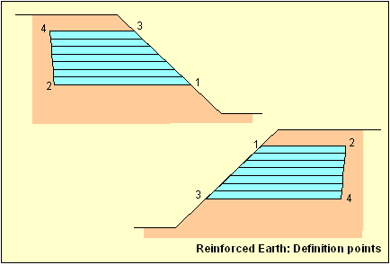
· ~CFGET – FOUNDAT (ENTNUM is the foundation number)
~CFGET, Par, FOUNDAT, ENTNUM, Lab1, Lab2, Lab3, IDX1, IDX2, IDX3
Lab1= ELEMLab3, IDX1, IDX2, IDX3
Retrieves general data relative to the elements of the foundation introduced in field ENTNUM. The data available for retrieve will be introduced in parameter Lab2.
|
Lab2 |
Description |
|
COUNT |
Number of foundation elements. |
|
EFS |
Ballast module of the element introduced in IDX1. |
|
NODE |
Node number according to ANSYS to which it corresponds the local node number (nnode) introduced in IDX2 of the element introduced in IDX1. 1 £ nnode £ 8 |
Lab1= NODE
~CFGET, Par, FOUNDAT, ENTNUM, NODE, Lab2, , IDX1, IDX2, IDX3
Retrieves data relative to the nodes of the elements of the foundation introduced in field ENTNUM. The data available for retrieve will be introduced in parameter Lab2.
|
Lab2 |
Description |
|
COUNT |
Number of foundation nodes. |
|
EFS |
Ballast module of the node introduced in IDX1. |
|
X |
X coordinate of the node introduced in IDX1. |
|
Y |
Y coordinate of the node introduced in IDX1. |
|
Z |
Z coordinate of the node introduced in IDX1. |
|
MAX |
Node with maximum ballast module. |
|
MIN |
Node with minimum ballast module. |
|
MED |
Node with ballast module closest to the mean value. |
Lab1= MAT
~CFGET, Par, FOUNDAT, ENTNUM, MAT, Lab2, , IDX1, IDX2, IDX3
Retrieves data relative to the soil materials that have an influence on the foundation introduced in field ENTNUM. The data available for retrieve will be introduced in parameter Lab2.
|
Lab2 |
Description |
|
EM |
Mean elastic modulus. |
|
NUM |
Mean Poisson coefficient. |
Lab1= EFS
~CFGET, Par, FOUNDAT, ENTNUM, EFS, Lab2, , IDX1, IDX2, IDX3
Retrieves data relative to the elastic foundation stiffness corresponding to the foundation introduced in field ENTNUM. The data available to retrieve will be introduced in parameter Lab2.
|
Lab2 |
Description |
|
MAX |
Maximum ballast module in the foundation. |
|
MIN |
Minimum ballast module in the foundation. |
|
MED |
Mean ballast module in the foundation. |
· ~CFGET – TERRAIN (ENTNUM is the foundation number)
~CFGET, Par, TERRAIN, ENTNUM, Lab1, Lab2, Lab3, IDX1, IDX2, IDX3
Lab1= LAYER
~CFGET, Par, TERRAIN, ENTNUM, LAYER, Lab2, , IDX1, IDX2, IDX3
Recovers data relative to terrain layers specified in ENTNUM. The different data to recover is introduced in the Lab2 label.
|
Lab2 |
Description |
||||
|
COUNT |
Number of layers that form the terrain. |
||||
|
MAT |
Number of the associated material to the layer introduced in IDX1. |
||||
|
THK |
Thickness of layer introduced in IDX1. |
||||
|
HBM |
Horizontal Ballast module of the layer introduced in IDX1. |
||||
|
KSEL |
Type of earth pressure in the layer introduced in IDX1:
|
Lab1= KCN
~CFGET, Par, TERRAIN, ENTNUM, KCN, , , IDX1, IDX2, IDX3
Reference number of the axis system where the terrain is being defined.
Lab1= DIR
~CFGET, Par, TERRAIN, ENTNUM, DIR, , , IDX1, IDX2, IDX3
Direction of the height axis of the terrain.
Lab1= SURFLV
~CFGET, Par, TERRAIN, ENTNUM, SURFLV, , , IDX1, IDX2, IDX3
Upper terrain height.
Lab1= WKEY
~CFGET, Par, TERRAIN, ENTNUM, WKEY, , , IDX1, IDX2, IDX3
Identifies ground-water level influence (0 – Does not consider the ground-water level, 1 – Takes into account the ground-water level).
Lab1= WH
~CFGET, Par, TERRAIN, ENTNUM, WH, , , IDX1, IDX2, IDX3
Height of the ground-water level.
Lab1= BETA
~CFGET, Par, TERRAIN, ENTNUM, BETA, , , IDX1, IDX2, IDX3
Angle of the terrain slope (sexagesimal degrees).
Lab1= Q
~CFGET, Par, TERRAIN, ENTNUM, Q, , , IDX1, IDX2, IDX3
Surface load.
Lab1= NAME
~CFGET, Par, TERRAIN, ENTNUM, NAME, , , IDX1, IDX2, IDX3
Name of the terrain. IDX1 indicates the eight-character group to recover. If the name is longer than eight characters, the following eight will be recovered indicating in IDX1 the next group. Due that the maximum number of characters is 32 IDX1 can take as values 1, 2, 3 or 4.
· ~CFGET – WALL (ENTNUM is not used)
~CFGET, Par, WALL, ENTNUM, Lab1, Lab2, Lab3, IDX1, IDX2, IDX3
Lab1= UTER
~CFGET, Par, WALL, , UTER, , , IDX1, IDX2, IDX3
Retrieves the associated terrain to the retaining wall. The retaining wall number is specified in IDX1.
Lab1= NSEC
~CFGET, Par, WALL, , NSEC, , , IDX1, IDX2, IDX3
Number of sections that define the retaining wall. The retaining wall number is specified in IDX1.
Lab1= NSTEP
~CFGET, Par, WALL, , NSTEP, , , IDX1, IDX2, IDX3
Number of calculus steps.
Lab1= NWALL
~CFGET, Par, WALL, , NWALL, , , IDX1, IDX2, IDX3
Number of retaining walls.
Lab1= COORD
~CFGET, Par, WALL, , COORD, Lab2, , , IDX1, IDX2, IDX3
Recovers data relative to the retaining wall coordinates. The different data to recover is introduced in the Lab2 label.
|
Lab2 |
Description |
|
X |
X coordinate of the retaining wall. |
|
YMAX |
Y max coordinate of the retaining wall |
|
YMIN |
Y min coordinate of the retaining wall |
· ~CFGET – BRIDGE (ENTNUM is not used)
~CFGET, Par, BRIDGE, ENTNUM, Lab1, Lab2, Lab3, IDX1, IDX2, IDX3
Lab1= VEHICLE
~CFGET, Par, BRIDGE, , VEHICLE, Lab2, , , IDX1, IDX2, IDX3
Recovers data relative to the bridge module. The different data to retrieve is introduced in the Lab2 label
|
Lab2 |
Description |
||||
|
ROWS |
Wheels rows number. The number of the vehicle is specified in IDX1. |
||||
|
COLS |
Wheels columns number. The number of the vehicle is specified in IDX1 |
||||
|
TYPE |
Vehicle type. The vehicle number is specified in IDX1.
|
||||
|
D |
Exempt distance after the vehicle has pass. The number of the vehicle is specified in IDX1 |
||||
|
START |
Part of the vehicle that remains out of the bridge at beginning of the generation. The vehicle number is specified in IDX1 |
||||
|
END |
Part of the vehicle that remains over the bridge at beginning of the generation. The vehicle number is specified in IDX1 |
||||
|
LOC |
Coordinates of the centre. The coordinates to obtain (X,Y) are indicated in Lab 3. The vehicle number is specified in IDX1 |
||||
|
CSP |
Spacing between columns. The vehicle number is specified in IDX1.The column number is introduced in IDX2. |
||||
|
RSP |
Spacing between rows. The vehicle number is specified in I IDX1. The row number is introduced in IDX2. |
||||
|
Q |
Loads per wheel. The vehicle number is specified in IDX1. The row number is introduced in IDX2.The column number is introduced in IDX3. |
||||
|
NUMBER |
Number of vehicles. |
||||
|
MAX |
Higher number of vehicle defined |
||||
|
NAME |
Name of the vehicle. The vehicle number is specified in IDX1. |
Lab1= FAMILY
~CFGET, Par, BRIDGE, , FAMILY, Lab2, , , IDX1, IDX2, IDX3
Recovers data relative to the defined families. The different data to recover is introduced in the Lab2 label.
|
Lab2 |
Description |
||||||||||||||||
|
TYPE |
Type of family. The family number is specified in IDX1.
|
||||||||||||||||
|
NLDCOMB |
Maximum number of loads that can take part of an internal combination. The number of the family is specified in IDX1. |
||||||||||||||||
|
NSTATES |
Number of start states that compose the family. The number of the family is specified in IDX1. |
||||||||||||||||
|
COEFT1I |
Multiplier Coefficient to apply to the load in the internal combinations when the load is favourable. The number of the family is specified in IDX1. |
||||||||||||||||
|
COEFT2I |
Multiplier Coefficient to apply to the load in the internal combinations when the load is unfavourable. The number of the family is specified in IDX1.. |
||||||||||||||||
|
STATES |
Start States that compose the family. The number of the family is specified in IDX1. |
||||||||||||||||
|
NUMBER |
Number of families. |
||||||||||||||||
|
MAX |
Highest number of Family defined |
Lab1= CABLE
~CFGET, Par, BRIDGE, , CABLE, Lab2, Lab3, IDX1, IDX2, IDX3
Retrieves data relative to the defined prestressed cables. The different data to recover is introduced in the Lab2 label.
|
Lab2 |
Description |
|
NPTS |
Number of points. The cable number is specified in IDX1. |
|
LS |
Load step in which has been introduced. If it is zero, indicates that load step is not yet defined. The cable number is specified in IDX1 and the point number in IDX2 |
|
LOC |
Coordinates of the point. The coordinates to obtain (X,Y,Z) are indicated in Lab 3. The cable number is specified in IDX1 and the point number in IDX2. |
|
TGIN |
Vector tangent to the stretch following the point. The coordinates to obtain (X,Y,Z) are indicated in Lab 3. The cable number is specified in IDX1 and the point number in IDX2. |
|
TGOUT |
Vector tangent to the stretch following the point. The coordinates to obtain (X,Y,Z) are indicated in Lab 3. The cable number is specified in IDX1 and the point number in IDX2. |
|
TENSION |
Cable tension in each point. The cable number is specified in IDX1 and the point number in IDX2. |
|
NUMBER |
Number of cables. |
|
MAX |
Highest number of cable defined |
Lab1= SECTION
~CFGET, Par, BRIDGE, , SECTION, Lab2, Lab3, IDX1, IDX2, IDX3
Retrieves data relative to the defined bridge cross sections. The different data to recover is introduced in the Lab2 label.
|
Lab2 |
Description |
||||||||||||||||||||||||||
|
TYPE |
Section type. The section number is specified in IDX1. Available only for slab section.
|
||||||||||||||||||||||||||
|
MAT |
Section’s material. The section number is specified in IDX1. |
||||||||||||||||||||||||||
|
NAME |
Name of the section. The section number is specified in IDX1. |
||||||||||||||||||||||||||
|
NPOINT |
Number of points in the cross section. The section number is specified in IDX1. Available only for slab sections. |
||||||||||||||||||||||||||
|
NHOLES |
Number of holes in the cross section. The section number is specified in IDX1. Available only for slab sections. |
||||||||||||||||||||||||||
|
NDIV |
Number of divisions in the cross section. The section number is specified in IDX1. Available only for slab sections. |
||||||||||||||||||||||||||
|
POINT |
Point coordinates. Available only for slab sections.
The section number is specified in IDX1 and the point in IDX2. |
||||||||||||||||||||||||||
|
HOLES |
Coordinates of the hole’s center. Available only for slab sections.
The section number is specified in IDX1 and the hole number in IDX2. |
||||||||||||||||||||||||||
|
DIV |
Number of division point. Available only for slab sections.
The cross section is specified in IDX1 and the division number in IDX2. |
||||||||||||||||||||||||||
|
DIM |
Value of the dimension of slab section IDX1. The dimension index is specified in IDX2 as it is described in the ~BRSSLAB parameters |
||||||||||||||||||||||||||
|
SHP |
Section shape. The section number is specified in IDX1.
|
||||||||||||||||||||||||||
|
NCELL |
Number of cells in section IDX1. Available only for box sections. |
||||||||||||||||||||||||||
|
KSYM |
Section IDX1 symmetry condition. Available only for box sections.
|
||||||||||||||||||||||||||
|
CELL |
Cell data. Available only for box sections.
The section number is specified in IDX1 and the cell number in IDX2. |
||||||||||||||||||||||||||
|
WEB |
Web data. Available only for box sections.
The section number is specified in IDX1 and the web number in IDX2.
|
||||||||||||||||||||||||||
|
FLANGE |
Flange section data. Available only for box sections.
The section number is specified in IDX1 and the flange number in IDX2.
|
||||||||||||||||||||||||||
|
CROWN |
Crown data. Available only for box sections.
|
Lab1= SMODEL
~CFGET, Par, BRIDGE, , SMODEL, Lab2, , IDX1, IDX2, IDX3
Retrieves data relative to the bridge solid modelling. The different data to recover is introduced in the Lab2 label.
|
Lab2 |
Description |
|
COUNT |
Gives the number of cross sections used in the solid modelling. |
|
MP |
Value of MP associated to the cross section. The MP number of the solid modelling is introduced in IDX1. |
|
NSEC |
Section number. The cross section number used in the solid modelling is introduced in IDX1. If the value is 0, the program calculates it. |
|
YOFF |
Offset in Y. The point of the solid modelling at which the value of the Y offset is to be retrieved is introduced in IDX1. |
|
ZOFF |
Offset in Z. The point of the solid modelling at which the value of the Z offset is to be retrieved is introduced in IDX1. |
|
BANK |
Bank. The point of the solid modelling at which the value of the bank is to be retrieved is introduced in IDX1 |
|
SKEW |
Skew angle. The point of the solid modelling at which the value of the skew angle is to be retrieved is introduced in IDX1. |
|
TRANS |
Transition between cross sections of the solid model. The point of the solid modelling at which the type of transition used is to be retrieved, is introduced in IDX1. |
|
CSYS |
Local coordinate system associated to ANSYS. The point of the solid modelling at which the local coordinate system is to be retrieved is introduced in IDX1. |
|
SOLID |
Identifies if the cross section used in the model is solid or hollow. The point of the solid modelling, at which the type of cross section used is to be retrieved, is introduced in IDX1. The output will be 0 for hollow sections and ¹0 if solid. |
Lab1= STRETCH
~CFGET, Par, BRIDGE, , STRETCH, Lab2, Lab3, IDX1, IDX2, IDX3
Retrieves data relative to the bridge stretch. The different data to recover is introduced in the Lab2 label.
|
Lab2 |
Description |
||||||||||||||
|
PLANT |
Stretch in plan view.
|
||||||||||||||
|
ELEV |
Point number at the cross section division.
|
||||||||||||||
|
PINI |
XYZ Coordinates XYZ of initial point. The chosen coordinate is introduced in IDX1. If the value is 1, the program will output the X coordinate of the initial point, if 2 the Y coordinate and 3 for Z coordinate. |
||||||||||||||
|
VINI |
XYZ Coordinates of the initial tangent vector. The chosen coordinate is introduced in IDX1. If the value is 1, the program will output the X coordinate of the initial tangent vector, if 2 the Y coordinate and 3 for Z coordinate. |
· ~CFGET – PRSCONC (ENTNUM is not used)
~CFGET, Par, PRSCONC, ENTNUM, Lab1, Lab2, Lab3, IDX1, IDX2, IDX3
Lab1= SBEAM
~CFGET, Par, PRSCONC, , SBEAM, Lab2, , IDX1, IDX2, IDX3
Retrieves data relative to the support beam. The different data to retrieve is introduced in the Lab2 label.
|
Lab2 |
Description |
|
TYPE |
Prestressing type (pre or post-tensioned). |
|
CSYS |
Active coordinate system where the support beam is captured. |
|
NTN |
Number of defined tendons. |
|
NCUT |
Number of support beam cuts. |
|
NPTY |
Number of control points of the elevation view. |
|
NPTZ |
Number of control points of the plan view. |
Lab1= TENDON
~CFGET, Par, PRSCONC, , TENDON, Lab2, Lab3, IDX1, IDX2, IDX3
Retrieves data relative to the defined tendons. The different data to retrieve is introduced in the Lab2 label.
|
Lab2 |
Lab3 |
Description |
||||||||||||||||||||||||||
|
COUNT |
|
Number of defined tendons. |
||||||||||||||||||||||||||
|
MAT |
|
Material number of tendon IDX1. |
||||||||||||||||||||||||||
|
ACTIVE |
|
Condition of tendon IDX1.
|
||||||||||||||||||||||||||
|
PNPTS |
|
Number of points in plan view of tendon IDX1. |
||||||||||||||||||||||||||
|
ENPTS |
|
Number of points in elevation view of tendon IDX1. |
||||||||||||||||||||||||||
|
ORDER |
|
Prestressing order of tendon IDX1. |
||||||||||||||||||||||||||
|
AREA |
|
Area of tendon IDX1. |
||||||||||||||||||||||||||
|
DIAMETER |
|
Diameter of the tendon IDX1 casing. |
||||||||||||||||||||||||||
|
P0MAX |
|
Initial force of tendon IDX1. |
||||||||||||||||||||||||||
|
P0 |
|
Anchorage force of tendon IDX1. |
||||||||||||||||||||||||||
|
METHOD |
|
Prestressing sequence of tendon IDX1:
|
||||||||||||||||||||||||||
|
PPOINTS |
|
User-defined number for the point in plan view of tendon IDX1 located at the position IDX2. |
||||||||||||||||||||||||||
|
EPOINTS |
|
User-defined number for the point in elevation view of tendon IDX1 located at the position IDX2. |
||||||||||||||||||||||||||
|
LOSS |
|
Losses of prestressing of tendon IDX1 at cut IDX2.The type of prestressing losses is specified at IDX3 and depends on the prestressing type: Pre-tensioned:
Post-tensioned:
|
||||||||||||||||||||||||||
|
COORD |
|
IDX1: Tendon number. |
||||||||||||||||||||||||||
|
|
X |
X coordinate of the tendon in this cut. |
||||||||||||||||||||||||||
|
|
Y |
Y coordinate of the tendon in this cut. |
||||||||||||||||||||||||||
|
|
Z |
Z coordinate of the tendon in this cut. |
||||||||||||||||||||||||||
|
|
SXY |
Tendon’s slope of XY plane. |
||||||||||||||||||||||||||
|
|
SXZ |
Tendon’s slope of XZ plane. |
Lab1= CUT
~CFGET, Par, PRSCONC, , CUT, Lab2, , IDX1, IDX2, IDX3
Retrieves the data related to the cuts of the support beam. The different data to retrieve is introduced in the Lab2 label.
|
Lab2 |
Description |
||||||||||||||||||||||||||
|
COUNT |
Number of cuts. |
||||||||||||||||||||||||||
|
X |
X coordinate of the cut IDX1 in the section coordinate system. |
||||||||||||||||||||||||||
|
Y |
Y coordinate of the cut IDX1 in the section coordinate system |
||||||||||||||||||||||||||
|
Z |
Z coordinate of the cut IDX1 in the section coordinate system |
||||||||||||||||||||||||||
|
DIST |
Distance from the beginning of the support beam to the cut IDX1. |
||||||||||||||||||||||||||
|
UPCOVER |
Top cover of cut IDX1. |
||||||||||||||||||||||||||
|
BOTCOVER |
Bottom cover of cut IDX1 |
||||||||||||||||||||||||||
|
NODE |
Node associated to cut IDX1 (only for beam models). |
||||||||||||||||||||||||||
|
LOSS |
Prestressing losses of tendon IDX1 at cut IDX2. The types of prestressing losses are specified at IDX3 and depends on the prestressing type: Pre-tensioned:
Post-tensioned:
|
Lab1= NODE
~CFGET, Par, PRSCONC, , NODE, Lab2, , IDX1, IDX2, IDX3
Retrieves the data related to the nodes associated to the support beam. The different data to retrieve is introduced in the Lab2 label.
|
Lab2 |
Description |
|
CUT |
Cut associated to the node IDX1 (only for beam models) |
Lab1= PPOINT
~CFGET, Par, PRSCONC, , PPOINT, Lab2, , IDX1, IDX2, IDX3
Retrieves the data related to the tendon’s points in plan view. The different data to retrieve is introduced in the Lab2 label.
|
Lab2 |
Description |
|
COUNT |
Number of points in plan view. |
|
X |
X coordinate of point IDX1 with respect to the origin of the support beam. |
|
Y |
Y coordinate of point IDX1 with respect to the section coordinate system. |
|
Z |
Y coordinate of point IDX1 with respect to the section coordinate system. |
|
SLOPE |
Slope defined in point IDX1. |
|
INFDIST |
Distance ratio of the inflection point of the tendon segment following point IDX1 (see ~PCPPDEF command). |
|
CUT |
Cut over which the point IDX1 is located. |
Lab1= EPOINT
~CFGET, Par, PRSCONC, , EPOINT, Lab2, , IDX1, IDX2, IDX3
Retrieves the data related to the tendon’s points in elevation view. The different data to retrieve is introduced in the Lab2 label.
|
Lab2 |
Description |
|
COUNT |
Number of points in elevation view. |
|
X |
X coordinate of point IDX1 with respect to the origin of the support beam. |
|
Y |
Y coordinate of point IDX1 with respect to the section coordinate system. |
|
Z |
Y coordinate of point IDX1 with respect to the section coordinate system. |
|
SLOPE |
Slope defined in point IDX1. |
|
INFDIST |
Distance ratio of the inflection point of the tendon segment following point IDX1 (see ~PCEPDEF command). |
|
CUT |
Cut over which the point IDX1 is located. |
Lab1= STLOSS
~CFGET, Par, PRSCONC, , STLOSS, Lab2, , IDX1, IDX2, IDX3
Retrieves the data related to the immediate prestressing losses calculation. The different data to retrieve is introduced in the Lab2 label.
|
Lab2 |
Description |
||||||
|
RELAX |
Calculation type of initial steel relaxation losses:
|
||||||
|
K |
Thermal reduction factor. |
||||||
|
LVAL |
Heating temperature variation. |
Lab1= LTLOSS
~CFGET, Par, PRSCONC, , LTLOSS, Lab2, , IDX1, IDX2, IDX3
Retrieves the data related to the long term prestressing losses calculation. The different data to retrieve is introduced in the Lab2 label.
|
Lab2 |
Description |
||||
|
LTAGE |
Calculation time for the long-term losses. |
||||
|
KOPT |
Losses calculation type:
|
||||
|
LABOPT |
Formulation used. |
||||
|
LVAL |
Value that depends on the calculation options (see ~PCLOSS command). |
~CFGET, Par, FRAME, ENTNUM, Lab1, , , IDX1, IDX2, IDX3
Lab1= NAME
~CFGET, Par, FRAME, ENTNUM, NAME , , , IDX1
Name assigned to the frame (32 characters). IDX1 indicates the group of 8 characters to recover.
|
IDX1 |
Characters |
|
1 |
1 to 8 |
|
2 |
9 to 16 |
|
3 |
17 to 24 |
|
4 |
25 to 32 |
Lab1= H
~CFGET, Par, FRAME, ENTNUM, H
Free height between slab and lintel.
Lab1= L
~CFGET, Par, FRAME, ENTNUM, L
Distance between piers.
Lab1= PTH
~CFGET, Par, FRAME, ENTNUM, PTH
Pier thickness.
Lab1= LTH
~CFGET, Par, FRAME, ENTNUM, LTH
Lintel thickness.
Lab1= STH
~CFGET, Par, FRAME, ENTNUM, STH
Slab thickness.
Lab1= LF
~CFGET, Par, FRAME, ENTNUM, LF
Left flange length.
Lab1= RF
~CFGET, Par, FRAME, ENTNUM, RF
Rigth flange length.
Lab1= HU
~CFGET, Par, FRAME, ENTNUM, HU
Vertical projection of the upper brackets
Lab1= VU
~CFGET, Par, FRAME, ENTNUM, VU
Horizontal projection of the upper brackets.
Lab1= HD
~CFGET, Par, FRAME, ENTNUM, HD
Vertical projection of the lower brackets
Lab1= VD
~CFGET, Par, FRAME, ENTNUM, VD
Horizontal projection of the lower brackets.
Lab1= HL
~CFGET, Par, FRAME, ENTNUM, HL
Terrain height over the lintel.
Lab1= HS
~CFGET, Par, FRAME, ENTNUM, HS
Terrain height over the slab.
Lab1= TGAMMA
~CFGET, Par, FRAME, ENTNUM, TGAMMA
Terrain specific weight.
Lab1= ST
~CFGET, Par, FRAME, ENTNUM, ST
Terrain mean stress in frames.
Lab1= FRIC
~CFGET, Par, FRAME, ENTNUM, FRIC
Terrain internal friction angle.
Lab1= KFS
~CFGET, Par, FRAME, ENTNUM, KFS
Balast module.
Lab1= REC
~CFGET, Par, FRAME, ENTNUM, REC
Geometrical cover.
Lab1= SEP
~CFGET, Par, FRAME, ENTNUM, SEP, , , IDX1, IDX2
Distance between reinforcements.
Lab1= FI
~CFGET, Par, FRAME, ENTNUM, FI, , , IDX1, IDX2
Diameter of the reinforcements.
Lab1= BENT
~CFGET, Par, FRAME, ENTNUM, BENT,,, IDX1, IDX2
Bending length.
Lab1= FOUND
~CFGET, Par, FRAME, ENTNUM, FOUND,,, IDX1
Length of the concrete foundations.
· ~CFGET – SEISM (ENTNUM = 0 or blank)
~CFGET, Par, SEISM, 0, Lab1, Lab2,, IDX1, IDX2,
Lab1 = NMODES
~CFGET, Par, SEISM, 0, NMODES
Number of modes extracted.
Lab1 = COMP
~CFGET, Par, SEISM, 0, COMP,,, IDX1
Spectrum component applied to each direction.
|
IDX1 |
Description |
|
1 |
X direction |
|
2 |
Y direction |
|
3 |
Z direction |
Lab1 = XDIR
~CFGET, Par, SEISM, 0, XDIR,,, IDX1
Components of the X-direction vector.
|
IDX1 |
Description |
|
1 |
X component |
|
2 |
Y component |
|
3 |
Z component |
Lab1 = YDIR
~CFGET, Par, SEISM, 0, YDIR,,, IDX1
Components of the Y-direction vector.
|
IDX1 |
Description |
|
1 |
X component |
|
2 |
Y component |
|
3 |
Z component |
Lab1 = ZDIR
~CFGET, Par, SEISM, 0, ZDIR,,, IDX1
Components of the Z-direction vector.
|
IDX1 |
Description |
|
1 |
X component |
|
2 |
Y component |
|
3 |
Z component |
Lab1 = COMP
~CFGET, Par, SEISM, 0, TYPE,,, IDX1
Spectrum type selected. Must be 1 or 2 according to the code used.
Lab1 = SPECT
~CFGET, Par, SEISM, 0, SPECT, Lab2,, IDX1, IDX2, IDX3
Data of the spectrum number IDX1.
|
Lab2 |
Description |
||||||
|
NPTH |
Number of defined points for the horizontal spectrum. |
||||||
|
NPTV |
Number of defined points for the vertical spectrum. |
||||||
|
DAMP |
Damping for which the spectrum has been defined. |
||||||
|
TH |
Periods for horizontal spectrum. IDX2 = 1, NPTH
|
||||||
|
SDH |
Values of the horizontal spectrum. IDX2 = 1, NPTH
|
||||||
|
TV |
Periods for vertical spectrum. IDX2 = 1, NPTV
|
||||||
|
SDV |
Values of the vertical spectrum. IDX2 = 1, NPTV
|
Lab1 = MODE
~CFGET, Par, SEISM, 0, MODE, Lab2,,IDX1, IDX2
Data about the modal spectral analysis.
|
Lab2 |
Description |
||||||||
|
FREC |
Frequency of mode IDX1 |
||||||||
|
PERI |
Period of mode IDX1 |
||||||||
|
FACT |
Participation factor of mode IDX1 for direction IDX2
|
||||||||
|
EFFM |
Effective mass of mode IDX1 for direction IDX2
|
Lab1 = PUSH
~CFGET, Par, SEISM, 0, PUSH, Lab2,,IDX1, IDX2
Data about the Push Over analysis.
|
Lab2 |
Description |
||||||
|
PP |
Performance point
|
||||||
|
IP |
Inelastic point
|
||||||
|
EP |
Elastic point
|
||||||
|
NPTCSC |
Number of points of the Capacity Spectrum Curve |
||||||
|
NPTDSC |
Number of points of the Demand Spectrum Curve |
||||||
|
CSC |
Capacity Spectrum Cuve. IDX1 = 1, NPTCSC
|
||||||
|
DSC |
Demand Spectrum Cuve. IDX1 = 1, NPTDSC
|
Menu Path
This command is not available through menu.
¾¾¾¾¾¾¨¾¾¾¾¾¾