

Suspension Bridge Generator
This CivilFEM utility allows generating the geometry with the following characteristics:
- Bridge suspended or not.
- Symmetric or non symmetric bridge
- Three different possibilities for roadway deck section:
o Bridge Section: Slab or Box.
o Solid Section.
o Pattern.
- Bridge is divided in three zones which are:
o Beginning or left segment.
o Central.
o Ending or right segment.
All zones consist of straight path and in elevation view are straight lines or parabolas.
When it is a cable-stayed bridge, structure has two towers, each one with one or two lintels where cables are anchored to.
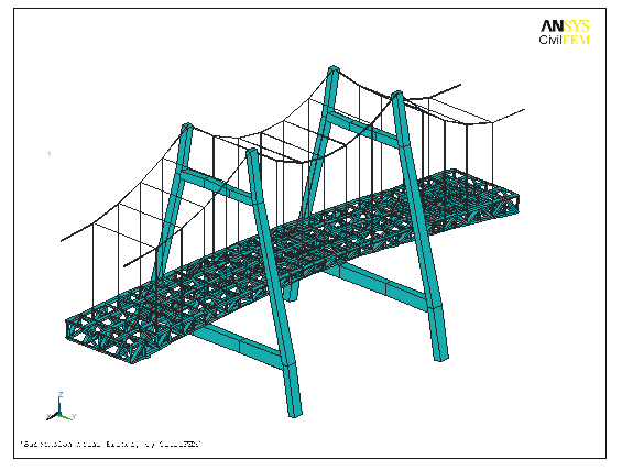
In the generated bridge 3D model all norms and conventions used in Bridges Module are kept up and , as well, all utilities for load generation are applicable.
In next chapters all considered typologies will be explained.
1 BRIDGES GENERATED WITH A BRIDGE SECTION
1.1 TYPOLOGIES
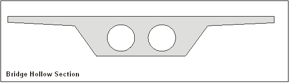
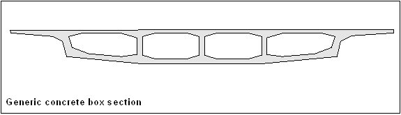
The sections admissible, slab or box, are generated with the Bridge Module.
1.2 USING THE GENERATOR
Before using the generador, all these steps must be defined:
- Units System.
- Materials: Concrete, Reinforcing Steel and Prestressing Steel.
- Element types for main cables, suspenders and towers.
- Define the bridge section with CivilFEM Bridge Module
After that, the generator window appears with the ~BRPD, FileName command
or using the Main Menu path:
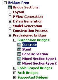
Civil Preprocessor > Bridges Prep > Predesigned bridges > Concrete Suspension Bridge
1.3 FILLING IN DATA IN GENERATOR WINDOW
The Suspension Bridge Generator Window for a Concrete Section is divided in General data for the whole bridge and specific for left, central and right segment. All parameters are explained in next step.
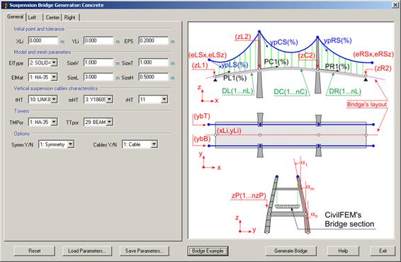
1.4 DATA EXPLANATION
Taking into account the next figure, all parameters are explained below.
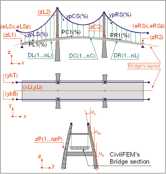
Initial point and tolerance:
|
XLi, YLi |
X, Y coordinates of initial left point of the bridge. |
|
EPS |
Tolerance for nodes. |
Model and meshing parameters:
|
EIType |
Element type (necessary SOLID45). |
|
EIMat |
Element material. |
|
SIZEV, SIZET, SIZEL, SIZEH |
Size of vertical, transverse, longitudinal and holes divisions, respectively. |
Parameters of symmetry and typology:
|
Symm Y/N |
1 if symmetric. 0 otherwise. |
|
Cables Y/N |
1 if it is a suspension bridge. 0 only bridge deck, not in suspension. |
Left, center and right segments:
|
DL, DC, DR |
Array of lengths in left, central and right segments, respectively. The first and the last points of the bridge are free. Distances should be separated by ',' and may be repeated with '@'. Example: 4.5, 6@3.5, 4.5 are the same as: 4.5, 3.5, 3.5, 3.5, 3.5, 3.5, 3.5, 4.5 |
|
PL1, PC1, PR1 |
Slope at the beginning of left, central and right segments, respectively (positive up). |
|
SL1, SLm, SL2 |
Sections at beginning, middle and final, respectively of left segment. |
|
SCm, SC2 y SRm, SR2 |
Middle and final sections in central and right segments, respectively. |
|
TrL, TrC, TrR |
Tangent of left, central and right segments, respectively ( 0 for smooth; 1 for discontinue). |
|
ZL1 |
Height at the beginning of left segment. |
|
ZL2, ZC2, ZR2 |
Height at the end of left, central and right segments, respectively. |
Cables characteristics:
|
tHL, tHC, tHR |
Hanger type at left, central and right segments, respectively. |
|
mHL, mHC, mHR |
Hanger material at left, central and right segments, respectively. |
|
rHL, rHC, rHR |
Real constants at left, central and right segments, respectively. |
|
tHT |
Vertical suspension cable type. |
|
mHT |
Vertical suspension cable material. |
|
rHT |
Vertical suspension cable real constants. |
Anchorage location:
|
eLSx, eLSz |
X, Z initial coordinates of top left hanger. |
|
eRSx, eRSz |
X, Z initial coordinates of top right hanger. |
|
ybLT, ybLB |
Y coordinate of top and bottom left hanger. |
|
ybRT, ybRB |
Y coordinate of top and bottom right hanger. |
|
ypLS, ypCS, ypRS |
Initial slope of left, central and right segment cables (%). |
Towers inclination:
|
AlphaLt , AlphaLm , AlphaLb |
Top, middle (between lintels) and bottom left tower angle with vertical (º). |
|
AlphaRt , AlphaRm , AlphaRb |
Top, middle (between lintels) and bottom left tower angle with vertical (º). |
Towers:
|
TMPor |
Tower material type. |
|
Ttpor |
Tower element type. |
|
zPL(),zPR() |
Array of heights of the divisions in left and right columns tower, respectively. Heights should be separated by ',' Example: 0.5 , 2.3 , 5.0 , 6.2 , 7.5 |
|
sPL(),sPR() |
Beam&Shell properties of left and right columns tower, respectively. |
|
DTLyn, DTRyn |
Value equal to 1 generates top lintel in left and right columns tower, respectively. |
|
DBLyn, DBRyn |
Value equal to 1 generates bottom lintel in left and right columns tower, respectively. |
|
NDivDL, NDivDR |
Number of divisions in left and right lintels, respectively. |
|
BPDTL, BPDBL |
Beam&Shell properties of top and bottom lintels, respectively, of left segment. |
|
BPDTR, BPDBR |
Beam&Shell properties of top and bottom lintels, respectively, of right segment. |
|
PzDTL, PzDBL |
Number of division in zPL() for top and bottom left lintel, respectively. |
|
PzDTR, PzDBR |
Number of division in zPR() for top and bottom right lintel, respectively. |
2 BRIDGES GENERATED WITH A SOLID SECTION
2.1 TYPOLOGY
The cross section is first modeled with ANSYS and then captured as a Solid Section with CivilFEM.
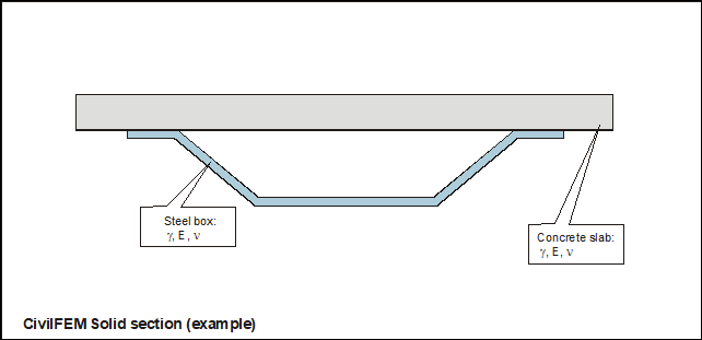
In bridge solid generation, linear elements are converted into shell elements and 2D elements into brick.
2.2 USING THE GENERATOR
Before using the generator, all these steps must be defined:
- Units System.
- Materials: Concrete, Reinforcing Steel and Prestressing Steel.
- Element types for main cables, suspenders and towers.
- Model definition of the generic section.
- Cross section capture.
After that, the generator window is shown with the ~BRPD, FileName command.
or using the Main Menu path:
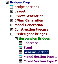
Civil Preprocessor > Bridges Prep > Predesigned bridges > Generic Suspension Bridge
2.3 FILLING IN DATA IN GENERATOR WINDOW
The Suspension Bridge Generator Window for a Generic Section is divided in General data for the whole bridge and specific for left, central and right segment. All parameters are explained in next step.
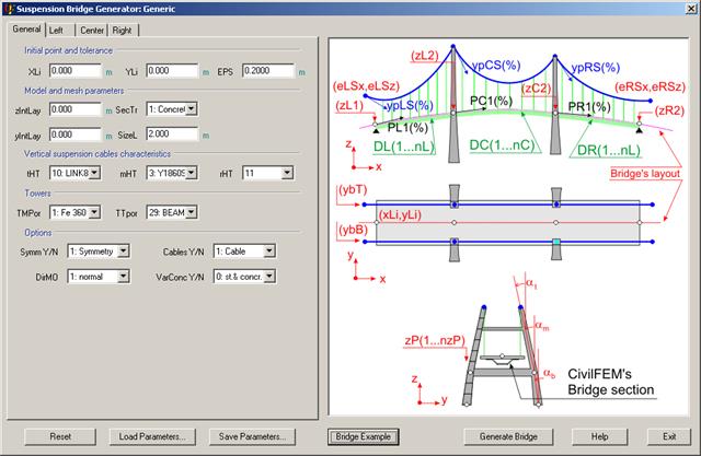
2.4 DATA EXPLANATION
Taking into account the next figure, all parameters are explained below.
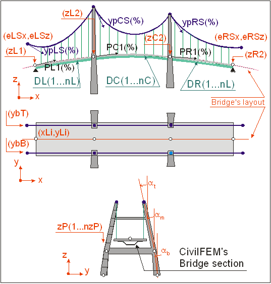
For more clarity and less redundancy, only specific parameters for a generic section are explained because
The rest of them were defined in last chapter.
Model and meshing parameters:
|
SecTr |
Generic section of the bridge. |
|
ZintLay, YIntLay |
Y, Z coordinates of intersection point between section and bridge axis. |
|
SizeL |
Size of longitudinal divisions in bridge section. |
Parameters of symmetry and tipology:
|
Symm Y/N |
1 if symmetric. 0 otherwise. |
|
Cables Y/N |
1 if it is a suspension bridge. 0 only bridge deck, not in suspension. |
|
VarConc Y/N |
0 to apply edge variation to steel and concrete. 1 to apply edge variation only to steel. |
|
DirMO |
1 sets section normal to deck. 0 sets section in YZ global plane. |
Left, center and right segments :
|
DL, DC, DR |
Array of lengths in left, central and right segments, respectively. The first and the last points of the bridge are free. Distances should be separated by ',' and may be repeated with '@'.Example: 4.5 , 6@3.5 , 4.5 is the same as: 4.5 , 3.5 , 3.5 , 3.5 , 3.5 , 3.5 , 3.5 , 4.5 |
|
PL1, PC1, PR1 |
Slope at the beginning of left, central and right segments, respectively (positive up). |
|
CL1, CLm, CL2 |
Deck thickness at the beginning, middle and final, respectively of left segment. |
|
CCm, CC2 and CRm, CR2 |
Middle and final deck thickness in central and right segments, respectively. |
|
ZL1 |
Height at the beginning of left segment. |
|
ZL2, ZC2, ZR2 |
Height at the end of left, central and right segments, respectively. |
3 BRIDGES GENERATED WITH A PATTERN SKETCH
3.1 TYPOLOGY
The admissible sections are the ones generated starting from a pattern or bars module.
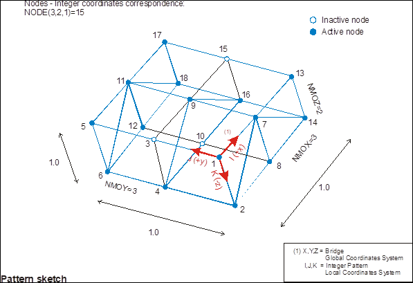
A pattern is just a group of bars joining nodes defined inside a cube-shaped mesh.
Definition of a pattern consists of:
- Separation between normal planes to axes I, J, K, when nodes intersect each other.
- Connection between net nodes, which will be the pattern bars.
- Bars characteristics.
3.2 USING THE GENERATOR
Before using the generator, all these steps must be defined:
- Units System.
- Materials: Concrete, Reinforcing Steel and Prestressing Steel.
- Element types for main cables, suspenders, pattern bars and towers.
- Model definition of the generic section.
- Cross section capture.
After that, the generator window is shown with the ~BRPD, FileName command
or using the Main Menu path:
Civil Preprocessor > Bridges Prep > Predesigned bridges > Steel Suspension Bridge
3.3 FILLING IN DATA IN GENERATOR WINDOW
The Suspension Bridge Generator Window for a Steel Section is divided in General data for the whole bridge and specific for left, central and right segment. All parameters are explained in next step.
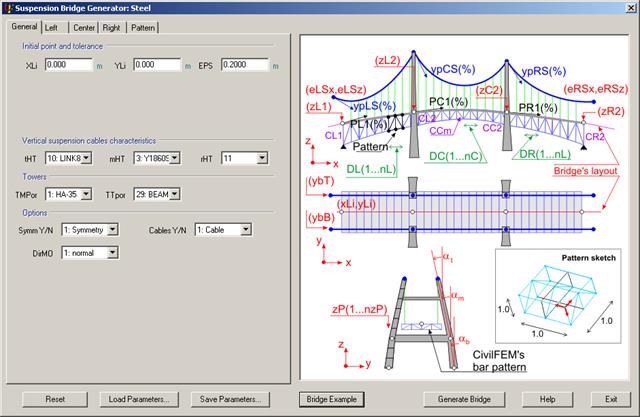
3.4 DATA EXPLANATION
Taking into account the next figure, all parameters are explained below.
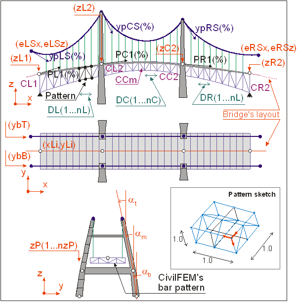
For more clarity and less redundancy, only specific parameters for a generic section are explained because
The rest of them were defined in previous chapters:
Pattern:
|
MoTyp |
Element type for pattern bars. |
|
MatMO |
Elements material for pattern bars. |
|
W_Deck |
Deck width. |
|
OriNod |
Origin node of selected bar. |
|
DesNod |
Destination node of selected bar. |
|
MoCon |
If it equals 0 there is no bar between these two nodes otherwise it is the Beam & Shell properties number of the bar. |
|
ModvX() |
Array of relative X coordinates of the divisions in the pattern. |
|
ModvY() |
Array of relative Y coordinates of the divisions in the pattern. |
|
ModvZ() |
Array of relative Z coordinates of the divisions in the pattern. The first relative coordinate has to be 0.0 and the last 1.0. A negative value in a position between second and penultimate indicates that the deck is not hanged on that point. |
Left, center and right segments :
|
DL, DC, DR |
Array of lengths in left, central and right segments, respectively. The first and the last points of the bridge are free. Distances should be separated by ',' and may be repeated with '@'.Example: 4.5 , 6@3.5 , 4.5 is the same as: 4.5 , 3.5 , 3.5 , 3.5 , 3.5 , 3.5 , 3.5 , 4.5 |
|
PL1, PC1, PR1 |
Slope at the beginning of left, central and right segments, respectively (positive up). |
|
CL1, CLm, CL2 |
Deck thickness at the beginning, middle and final, respectively of left segment. |
|
CCm, CC2 and CRm, CR2 |
Middle and final deck thickness in central and right segments, respectively. |
|
ZL1 |
Height at the beginning of left segment. |
|
ZL2, ZC2, ZR2 |
Height at the end of left, central and right segments, respectively. |
4 BRIDGES GENERATED WITH A MIXED SECTION 1
4.1 TYPOLOGY
This is a particular case of bridges generated with a solid section where section is composed of a concrete slab over I-section steel beams:
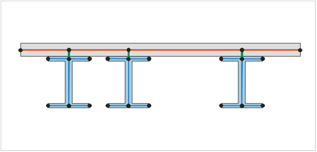
4.2 USING THE GENERATOR
Before using the generator, all these steps must be defined:
- Units System.
- Materials and element types for hangers, cables, bracings and towers.
- Cross sections and Beam & Shell properties.
After that, the generator window is shown with the ~BRPD, FileName command.
or using the Main Menu path:
Civil Preprocessor > Bridges Prep > Predesigned bridges > Mixed Section type 1
4.3 FILLING IN DATA IN GENERATOR WINDOW
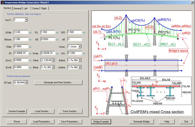
The Suspension Bridge Generator Window for Mixed Section is divided in the section definition (slab over beams), general data for the whole bridge and specific for left, central and right segment. All parameters are explained in next step.
4.4 DATA EXPLANATION
Taking into account the next figure, all parameters are explained below.
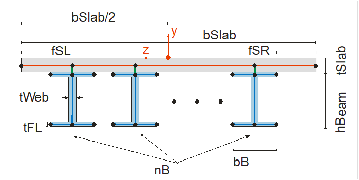
For more clarity and less redundancy, only specific parameters for a generic section are explained because the rest of them were defined in last chapter.
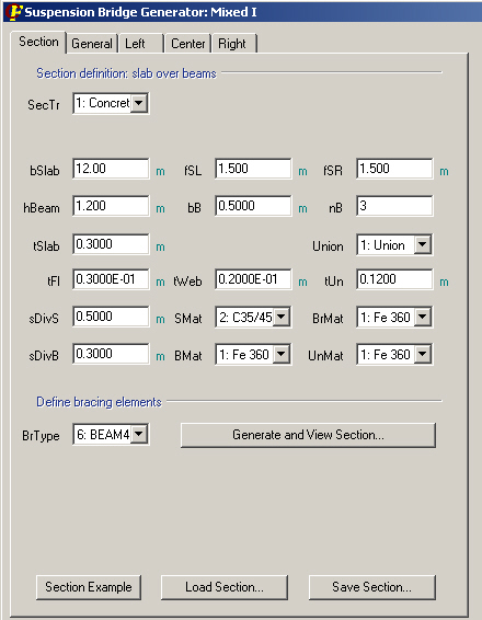
Section Definition:
|
SecTr |
Number for the new section of the bridge |
|
bSlab |
Total width of upper slab |
|
fSL |
Slab left flange lenght |
|
fSR |
Slab right flange lenght |
|
hBeam |
Height of I beam |
|
tSlab |
Upper slab thickness |
|
tFl |
I beam's flange thickness |
|
tWeb |
I beam's web thickness |
|
Union |
1: Create dummy union elements 0: No create |
|
tUn |
Union element thickness |
|
sDivS, sDivB |
Slab and beam divisions size |
|
SMat, BMat |
Slab and beam material |
|
BrMat |
Beam material |
|
UnMat |
Union elements material |
Define bracing elements:
|
BrType |
Bracing element type |
After defining the previous parameters, usar can generate and view the mixed section by pressing the button:

The following window appears:
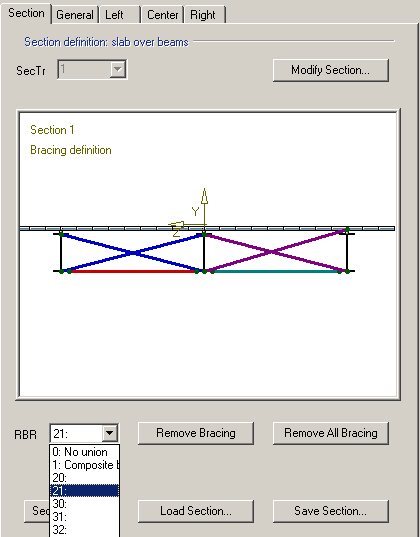
In this window new bracings can be created, removed or Beam & Shell properties modificated.
Buttons
|
Section Example |
Loads a mixed section example |
|
Load Section… |
Loads a mixed section |
|
Save Section… |
Saves a mixed section |
5 BRIDGES GENERATED WITH A MIXED SECTION 2
5.1 TYPOLOGY
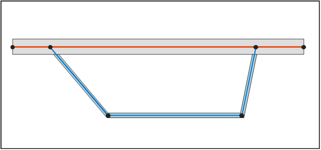
This is a particular case of bridges generated with a solid section where section is composed of a concrete slab over a steel box.
5.2 USING THE GENERATOR
Before using the generator, all these steps must be defined:
- Units System.
- Materials and element types for hangers, cables, bracings and towers.
- Cross sections and Beam & Shell properties.
After that, the generator window is shown with the ~BRPD, FileName command.
or using the Main Menu path:
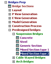
Civil Preprocessor > Bridges Prep > Predesigned bridges > Mixed Section type 2
5.3 FILLING IN DATA IN GENERATOR WINDOW
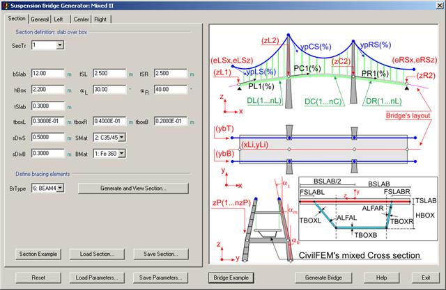
The Suspension Bridge Generator Window for Mixed Section is divided in the section definition (slab over beams), general data for the whole bridge and specific for left, central and right segment. All parameters are explained in next step.
5.4 DATA EXPLANATION
Taking into account the next figure, all parameters are explained below.
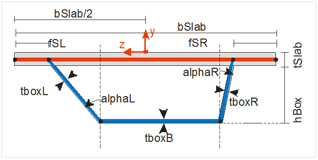
For more clarity and less redundancy, only specific parameters for a generic section are explained because the rest of them were defined in last chapter.
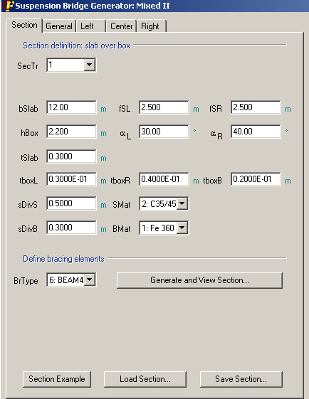
Section Definition:
|
SecTr |
Number for the new section of the bridge |
|
bSlab |
Total width of upper slab |
|
fSL |
Slab left flange lenght |
|
fSR |
Slab right flange lenght |
|
hBox |
Box height |
|
tSlab |
Upper slab thickness |
|
αL, αR |
Angles with vertical of left and right side of the box |
|
tboxL,tboxR |
Thicknesses of left and right sides of the box |
|
tboxB |
Thickness of box bottom |
|
sDivS, sDivB |
Slab and beam divisions size |
|
SMat, BMat |
Slab and beam materials |
Define bracing elements:
|
BrType |
Bracing element type |
After defining the previous parameters, usar can generate and view the mixed section by pressing the button:
The following window appears:
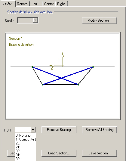
In this window new bracings can be created, removed or Beam & Shell properties modificated.
Buttons
|
Section Example |
Loads a mixed section example |
|
Load Section… |
Loads a mixed section |
|
Save Section… |
Saves a mixed section |
Related commands: