

~DIMCON
~DIMCON, Lab1, Lab2, DIRKEY, WMIN, WMAX, VAL1, VAL2, VAL3, VAL4, VAL5, VAL6, VAL7, VAL8, VAL9, VAL10
Designs reinforced concrete cross sections and reinforced concrete shell vertices
POST1: Concrete Checking
Lab1, Lab2
Design type. These labels are related with the CHCKTYPE label used to retrieve results.
DIRKEY
Identity key of the bending plane or shear direction to be designed.
WMIN
Minimum allowable amount of reinforcement wmin in the design under axial force+biaxial bending. In the design process the program will always take a reinforcement equal or higher than WMIN times the initially arranged in the section. This value must always be equal or higher to 0. By default, WMIN = 0.5
WMAX
Maximum allowable amount of reinforcement wmax in the design under axial force+biaxial bending. In the design process the program will always take a reinforcement equal or lower than WMAX times the initially arranged in the section. This value must always be equal or higher to WMIN. By default, WMAX = 2
VAL1, VAL2, VAL3 ... VAL10
Arguments used to specify certain design options.
Lab1= SHT
~DIMCON, SHT, Lab2, DIRKEY, WMIN, WMAX, , , VAL3, , , , , , VAL9
Designs for shear and torsion on reinforced concrete cross sections. Valid labels are:
|
Lab2 |
Description |
|
SHEAR |
Only shear design. Not taken into account torsional movement. (CHCKTYPE = DS_SH). |
|
TORSION |
Only torsional design. Not taken into account shear force. (CHCKTYPE = DS_TR). |
|
BOTH |
Combined shear and torsional design. Default value. (CHCKTYPE = DS_SHTR). |
|
DIRKEY |
Description |
|
0 |
Shear design in element Y direction (shear QY). Default value. |
|
1 |
Shear design in element Z direction (shear QZ). |
WMIN and WMAX are only used for the IS456 code design.
If the active code is ACI 349-01:
|
VAL3 |
Type of analysis (different shear and torsion strength reduction factors are used in each case). |
|
0 |
Strength of joints (f = 0.60). Default value. |
|
1 |
Other cases (f = 0.85). |
If the active code is ACI 349-01 or ACI 318-05:
|
VAL9 |
Maximum steel strength force |
|
0 |
Restricts the value of the strength force up to the maximum provided in the code. Default value. |
|
1 |
Strength force limitation ignored. |
Lab1= SHT_HSL (only for GB50010)
~DIMCON, SHT_HSL, Lab2, DIRKEY
Designs for shear and torsion on reinforced concrete cross sections assuming that the forces and moments come from seismic loads. Valid labels are:
|
Lab2 |
Description |
|
SHEAR |
Only shear design. Not taken into account torsional movement. (CHCKTYPE = DS_SH). |
|
TORSION |
Only torsional design. Not taken into account shear force. (CHCKTYPE = DS_TR). |
|
BOTH |
Combined shear and torsional design. Default value. (CHCKTYPE = DS_SHTR). |
|
DIRKEY |
Description |
|
0 |
Shear design in element Y direction (shear QY). Default value. |
|
1 |
Shear design in element Z direction (shear QZ). |
Lab1= 3D_RF or 3DB
~DIMCON, 3D_RF, Lab2, , WMIN, WMAX, VAL1, VAL2, VAL3
Designs axial load + biaxial bending on reinforced concrete cross sections. Calculate a reinforcement factor for all the scalable reinforcement defined. (CHCKTYPE = DS_3D)
Lab2
For the ITER code:
|
Lab2 |
Description |
|
Blank or ULSR1 |
Strain limits specified in the material. |
|
ULSR3 |
Accidental conditions (ecu2 = 3.5 ‰, ecu = 2.0 ‰, eud = 45.0 ‰) |
|
ULSR6 |
Impact of general aviation plane (ecu2 = 5 ‰, ecu = 2.0 ‰, eud = 45.0 ‰) |
|
ULSR7 |
Load drops (ecu2 = 5 ‰, ecu = 2.0 ‰, eud = 45.0 ‰) |
|
SLSR1 |
Limited crackwidths (ecu2 = 0.60 fck/E, ecu = 0.45 fck/E, eud = smax/E)
(*) For fctm a value of 2.896 MPa is considered (equivalent to a fck = 30 MPa concrete) |
|
SLSR2 |
Limitation of stresses (ecu2 = 0.60 fck/E, ecu = 2.0 ‰, eud = 0.8 fyk/E) |

In these cases, VAL1 and VAL2 are ignored.
For the rest of the codes Lab2 is ignored.
VAL1
Maximum allowable stress in concrete.
VAL2
Maximum allowable stress in longitudinal reinforcement.
VAL3
Type of member (different strength reduction factors for axial compression, and axial compression with flexure are used in each case).
If the active code is ACI 318-05:
|
1 |
Members with spiral reinforcement (f = 0.70). |
|
0 |
Other cases (f = 0.65). Default value |
If the active code is ACI 349-01:
|
1 |
Members with spiral reinforcement (f = 0.75). |
|
0 |
Other cases (f = 0.70). Default value |
Lab1= 3D_DSGN
~DIMCON, 3D_DSGN, Lab2, , WMIN, WMAX, VAL1, VAL2, VAL3
Designs axial load + biaxial bending on reinforced concrete cross sections. Calculate the amount of reinforcement for the reinforcement groups defined. (CHCKTYPE = DS_3D)
Lab2
For the ITER code:
|
Lab2 |
Description |
|
Blank or ULSR1 |
Strain limits specified in the material. |
|
ULSR3 |
Accidental conditions (ecu2 = 3.5 ‰, ecu = 2.0 ‰, eud = 45.0 ‰) |
|
ULSR6 |
Impact of general aviation plane (ecu2 = 5 ‰, ecu = 2.0 ‰, eud = 45.0 ‰) |
|
ULSR7 |
Load drops (ecu2 = 5 ‰, ecu = 2.0 ‰, eud = 45.0 ‰) |
|
SLSR1 |
Limited crackwidths (ecu2 = 0.60 fck/E, ecu = 0.45 fck/E, eud = smax/E)
(*) For fctm a value of 2.896 MPa is considered (equivalent to a fck = 30 MPa concrete) |
|
SLSR2 |
Limitation of stresses (ecu2 = 0.60 fck/E, ecu = 2.0 ‰, eud = 0.8 fyk/E) |

In these cases, VAL1 and VAL2 are ignored.
For the rest of the codes Lab2 is ignored.
VAL1
Maximum allowable stress in concrete.
VAL2
Maximum allowable stress in longitudinal reinforcement.
VAL3
Type of member (different strength reduction factors for axial compression, and axial compression with flexure are used in each case).
If the active code is ACI 318-05:
|
1 |
Members with spiral reinforcement (f = 0.70). |
|
0 |
Other cases (f = 0.65). Default value |
If the active code is ACI 349-01:
|
1 |
Members with spiral reinforcement (f = 0.75). |
|
0 |
Other cases (f = 0.70). Default value |
Lab1= 2D_RF or 2DB
~ DIMCON, 2D_RF, Lab2, DIRKEY, WMIN, WMAX, VAL1, VAL2,VAL3
Designs axial load + bending on reinforced concrete cross sections. Calculate a reinforcement factor for all the scalable reinforcement defined (CHCKTYPE = DS_2D).
Lab2
For the ITER code:
|
Lab2 |
Description |
|
Blank or ULSR1 |
Strain limits specified in the material. |
|
ULSR3 |
Accidental conditions (ecu2 = 3.5 ‰, ecu = 2.0 ‰, eud = 45.0 ‰) |
|
ULSR6 |
Impact of general aviation plane (ecu2 = 5 ‰, ecu = 2.0 ‰, eud = 45.0 ‰) |
|
ULSR7 |
Load drops (ecu2 = 5 ‰, ecu = 2.0 ‰, eud = 45.0 ‰) |
|
SLSR1 |
Limited crackwidths (ecu2 = 0.60 fck/E, ecu = 0.45 fck/E, eud = smax/E)
(*) For fctm a value of 2.896 MPa is considered (equivalent to a fck = 30 MPa concrete) |
|
SLSR2 |
Limitation of stresses (ecu2 = 0.60 fck/E, ecu = 2.0 ‰, eud = 0.8 fyk/E) |
In these cases, VAL1 and VAL2 are ignored.
For the rest of the codes Lab2 is ignored.
Dirkey
|
DIRKEY |
Description |
|
0 |
Bending in XY local plane of element (Moments Mz). Default value. |
|
1 |
Bending in XZ local plane of element (Moments My). |
VAL1
Maximum allowable stress in concrete.
VAL2
Maximum allowable stress in longitudinal reinforcement.
VAL3
Type of member (different strength reduction factors for axial compression, and axial compression with flexure are used in each case).
If the active code is ACI 318-05:
|
1 |
Members with spiral reinforcement (f = 0.70). |
|
0 |
Other cases (f = 0.65). Default value |
If the active code is ACI 349-01:
|
1 |
Members with spiral reinforcement (f = 0.75). |
|
0 |
Other cases (f = 0.70). Default value |
Lab1= 2D_DSGN
~ DIMCON, 2D_DSGN, Lab2, DIRKEY, WMIN, WMAX, VAL1, VAL2,VAL3
Designs axial load + bending on reinforced concrete cross sections. Calculate the amount of reinforcement for the reinforcement groups defined. (CHCKTYPE = DS_2D).
Lab2
For the ITER code:
|
Lab2 |
Description |
|
Blank or ULSR1 |
Strain limits specified in the material. |
|
ULSR3 |
Accidental conditions (ecu2 = 3.5 ‰, ecu = 2.0 ‰, eud = 45.0 ‰) |
|
ULSR6 |
Impact of general aviation plane (ecu2 = 5 ‰, ecu = 2.0 ‰, eud = 45.0 ‰) |
|
ULSR7 |
Load drops (ecu2 = 5 ‰, ecu = 2.0 ‰, eud = 45.0 ‰) |
|
SLSR1 |
Limited crackwidths (ecu2 = 0.60 fck/E, ecu = 0.45 fck/E, eud = smax/E)
(*) For fctm a value of 2.896 MPa is considered (equivalent to a fck = 30 MPa concrete) |
|
SLSR2 |
Limitation of stresses (ecu2 = 0.60 fck/E, ecu = 2.0 ‰, eud = 0.8 fyk/E) |
In these cases, VAL1 and VAL2 are ignored.
For the rest of the codes Lab2 is ignored.
Dirkey
|
DIRKEY |
Description |
|
0 |
Bending in XY local plane of element (Moments Mz). Default value. |
|
1 |
Bending in XZ local plane of element (Moments My). |
VAL1
Maximum allowable stress in concrete.
VAL2
Maximum allowable stress in longitudinal reinforcement.
VAL3
Type of member (different strength reduction factors for axial compression, and axial compression with flexure are used in each case).
If the active code is ACI 318-05:
|
1 |
Members with spiral reinforcement (f = 0.70). |
|
0 |
Other cases (f = 0.65). Default value |
If the active code is ACI 349-01:
|
1 |
Members with spiral reinforcement (f = 0.75). |
|
0 |
Other cases (f = 0.70). Default value |
Lab1= SHELL
~ DIMCON, SHELL, Lab2, , , , VAL1, VAL2, VAL3, VAL4, VAL5, VAL6, VAL7, VAL8, VAL9, VAL10
Designs shell vertices. Valid labels are:
|
Lab2 |
Description |
||||||||||||||||||||
|
CEB |
Design according to the method specified in Model Code CEB-FIP 1990. (CHCKTYPE = DSHLCEB)
|
||||||||||||||||||||
|
WOOD |
Design according to Wood-Armer method. (CHCKTYPE = WOOD)
|
||||||||||||||||||||
|
VF |
Design according to the Orthogonal Directions method. (CHCKTYPE = DVF)
|
||||||||||||||||||||
|
MUD |
Design according to the Most Unfavorable Direction method. (CHCKTYPE = DMUD)
|
||||||||||||||||||||
|
SHEAR |
Design shear reinforcement according to the active code. (CHCKTYPE = SHDSH). If the active code is ACI 359-04:
If the active code is ACI 349-01:
If the active code is ACI 349-01 or ACI 318-05:
If the active code is EC2-08:
|
||||||||||||||||||||
|
IPSHEAR
|
Design in plane shear reinforcement according to the active code. (CHCKTYPE = IPSHDSH). If the active code is ACI 349-01:
|
||||||||||||||||||||
|
TNGSHR
|
Design tangential shear reinforcement (in plane shear) according to ACI 359-04 code. (CHCKTYPE =DS_TSH).
|
||||||||||||||||||||
|
BEND_AXL |
Design for flexure and axial loads according to ACI 359-04 code. (CHCKTYPE = DS_2D).
|
||||||||||||||||||||
|
BEND_SHR |
Design for flexure, axial, tangential and radial shear loads according to ACI 359-04 code. (CHCKTYPE =DS_2DSH).
|
||||||||||||||||||||
Notes
- Calculation results are stored in the CivilFEM results file as an alternative. The available results for cross sections are the following:
If active code is CEB:
|
CHCKTYPE |
DS_2D: Design under bending and axial force. |
|
Results |
Description |
|
CRT_TOT |
Section strength criterion. |
|
REINFACT |
Reinforcement factor. |
|
DS_OK |
Designed and not designed elements. |
|
CHCKTYPE |
DS_3D: Axial load + biaxial bending design. |
|
Results |
Description |
|
CRT_TOT |
Section strength criterion. |
|
REINFACT |
Reinforcement factor. |
|
DS_OK |
Designed and not designed elements. |
If active code is EC2-91:
|
CHCKTYPE |
DS_2D: Design under bending and axial force. |
|
Results |
Description |
|
CRT_TOT |
Section strength criterion. |
|
REINFACT |
Reinforcement factor. |
|
DS_OK |
Designed and not designed elements. |
|
CHCKTYPE |
DS_3D: Axial load + biaxial bending design. |
|
Results |
Description |
|
CRT_TOT |
Section strength criterion. |
|
REINFACT |
Reinforcement factor. |
|
DS_OK |
Designed and not designed elements. |
|
CHCKTYPE |
DS_SH: Shear design. |
|
Results |
Description |
|
VRD1 |
Design shear resistance without considering the reinforcement in the section (VRd1). |
|
CRVRD1 |
Ratio of the design shear force (VSd) to the resistance VRd1. |
|
VRD2 |
Maximum design shear force that can be carried without crushing of the concrete compressed struts (VRd2). |
|
CRVRD2 |
Ratio of the design shear force (VSd) to the resistance VRd2. |
|
VWD |
Contribution of the necessary shear reinforcement. |
|
ASSH |
Area per unit length of defined shear reinforcement. |
|
DS_OK |
Designed and not designed elements. |
|
CHCKTYPE |
DS_TR: Torsion design. |
|
Results |
Description |
|
TRD1 |
Maximum torsional moment that can be resisted by the compression struts of the concrete (TRd1). |
|
CRTRD1 |
Ratio of the design torsional moment (TSd) to the resistanceTRd1. |
|
ASTT |
Area per unit length of torsional transverse reinforcement defined. |
|
ASLT |
Total area of torsional longitudinal reinforcement defined. |
|
DS_OK |
Designed and not designed elements. |
|
CHCKTYPE |
DS_SHTR: Shear and torsion design. |
|
Results |
Description |
|
VRD1 |
Design shear resistance without considering the reinforcement in the section. |
|
CRVRD1 |
Ratio of the design shear force (VSd) to the resistance VRd1. |
|
VRD2 |
Maximum design shear force that can be carried without crushing of the concrete compressed struts. |
|
CRVRD2 |
Ratio of the design shear force (VSd) to the resistance VRd2. |
|
VWD |
Contribution of the necessary shear reinforcement. |
|
TRD1 |
Maximum torsional moment that can be resisted by the compression struts of the concrete. |
|
CRTRD1 |
Ratio of the design torsional moment (TSd) to the resistanceTRd1. |
|
CRTCST |
Criterion for the ultimate compression strength of the concrete due to combined shear and torsion. |
|
ASSH |
Area per unit length of defined shear reinforcement. |
|
ASTT |
Area per unit length of torsional transverse reinforcement defined. |
|
ASLT |
Total area of torsional longitudinal reinforcement defined. |
|
DS_OK |
Designed and not designed elements. |
If active code is EC2-08 or ITER:
|
CHCKTYPE |
DS_2D: Design under bending and axial force. |
|
Results |
Description |
|
CRT_TOT |
Section strength criterion. |
|
REINFACT |
Reinforcement factor. |
|
DS_OK |
Designed and not designed elements. |
|
CHCKTYPE |
DS_3D: Axial load + biaxial bending design. |
|
Results |
Description |
|
CRT_TOT |
Section strength criterion. |
|
REINFACT |
Reinforcement factor. |
|
DS_OK |
Designed and not designed elements. |
|
CHCKTYPE |
DS_SH: Shear design. |
|
Results |
Description |
|
VRDC |
Design shear resistance without considering the reinforcement in the section (VRd,c). |
|
CRT_1 |
Ratio of the design shear force (VEd) to the residtence VRd,c. |
|
VRDS |
Design shear resistence of shear reinforcement (VRd,s). |
|
VRDMAX |
Maximum design shear force that can be carried without crushing of the concrete compressed struts (VRd,max). |
|
CRT_3 |
Ratio of the shear force VEd to the resistance VRd,max. |
|
ASSH |
Area per unit length of defined shear reinforcement. |
|
DSG_CRT |
Designed and not designed elements. |
|
CHCKTYPE |
DS_TR: Torsion design. |
|
Results |
Description |
|
TRDMAX |
Maximum torsional moment that can be resisted by the compression struts of the concrete (TRd,max). |
|
CRT_1 |
Ratio of the design torsional moment (TEd) to the resistance TRd,max. |
|
TRD |
Maximum torsional moment that can be resisted by the torsional reinforcement (TRd). |
|
ASTT |
Area per unit length of torsional transverse reinforcement defined. |
|
ASLT |
Total area of torsional longitudinal reinforcement defined. |
|
DSG_CRT |
Designed and not designed elements. |
|
CHCKTYPE |
DS_SHTR: Shear and torsion design. |
|
Results |
Description |
|
VRDC |
Design shear resistance without considering the reinforcement in the section (VRd,c). |
|
CRT_1 |
Ratio of the design shear force (VEd) to the resistence VRd,c. |
|
VRDS |
Design shear resistence of shear reinforcement (VRd,s). |
|
VRDMAX |
Maximum design shear force that can be carried without crushing of the concrete compressed struts (VRd,max). |
|
CRT_3 |
Ratio of the shear force VEd to the resistance VRd,max. |
|
ASSH |
Area per unit length of defined shear reinforcement. |
|
TRDMAX |
Maximum torsional moment that can be resisted by the compression struts of the concrete (TRd,max). |
|
CRT_4 |
Ratio of the design torsional moment (TEd) to the resistance TRd,max. |
|
TRD |
Maximum torsional moment that can be resisted by the torsional reinforcement (TRd). |
|
ASTT |
Area per unit length of torsional transverse reinforcement defined. |
|
ASLT |
Total area of torsional longitudinal reinforcement defined. |
|
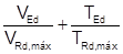
CRT_6 |
Resistance criterion to combined torsion and shear
|
|
DSG_CRT |
Designed and not designed elements. |
If active code is EHE-98 or EHE-08:
|
CHCKTYPE |
DS_2D: Design under bending and axial force. |
|
Results |
Description |
|
CRT_TOT |
Section strength criterion. |
|
REINFACT |
Reinforcement factor. |
|
DS_OK |
Designed and not designed elements. |
|
CHCKTYPE |
DS_3D: Axial load + biaxial bending design. |
|
Results |
Description |
|
CRT_TOT |
Section strength criterion. |
|
REINFACT |
Reinforcement factor. |
|
DS_OK |
Designed and not designed elements. |
|
CHCKTYPE |
DS_SH: Shear design. |
|
Results |
Description |
|
VU1 |
Ultimate shear resistance due to oblique compression of concrete in web. |
|
CRTVU1 |
Ratio of the design shear (Vrd) to the resistance Vu1. |
|
VCU |
Contribution of concrete to shear resistance. |
|
VSU |
Contribution of the web shear transverse reinforcement to the shear resistance. |
|
ASSH |
Area per unit length of defined shear reinforcement. |
|
DS_OK |
Designed and not designed elements. |
|
CHCKTYPE |
DS_TR: Torsion design. |
|
Results |
Description |
|
TU1 |
Maximum torsional moment that can be resisted without crushing due to compression of the concrete. |
|
CRTTU1 |
Ratio of the design torsional moment (TSd) to the resistance Tu1. |
|
ASTT |
Area per unit length of torsional transverse reinforcement defined. |
|
ASLT |
Total area of torsional longitudinal reinforcement defined. |
|
DS_OK |
Designed and not designed elements. |
|
CHCKTYPE |
DS_SHTR: Shear and torsion design. |
|
Results |
Description |
|
VU1 |
Ultimate shear resistance due to oblique compression of concrete in web. |
|
CRTVU1 |
Ratio of the design shear (Vrd) to the resistance Vu1. |
|
VCU |
Contribution of concrete to shear resistance. |
|
VSU |
Contribution of the web shear transverse reinforcement to the shear resistance. |
|
TU1 |
Maximum torsional moment that can be resisted without crushing due to compression of the concrete. |
|
CRTTU1 |
Ratio of the design torsional moment (TSd) to the resistance Tu1. |
|
CRTCST |
Criterion for the ultimate compression strength of the concrete due to combined shear and torsion. |
|
ASSH |
Area per unit length of defined shear reinforcement. |
|
ASTT |
Area per unit length of torsional transverse reinforcement defined. |
|
ASLT |
Total area of torsional longitudinal reinforcement defined. |
|
DS_OK |
Designed and not designed elements. |
If active code is ACI 318:
|
CHCKTYPE |
DS_2D: Design under bending and axial force. |
|
Results |
Description |
|
CRT_TOT |
Section strength criterion. |
|
REINFACT |
Reinforcement factor. |
|
DS_OK |
Designed and not designed elements. |
|
CHCKTYPE |
DS_3D: Axial load + biaxial bending design. |
|
Results |
Description |
|
CRT_TOT |
Section strength criterion. |
|
REINFACT |
Reinforcement factor. |
|
DS_OK |
Designed and not designed elements. |
|
CHCKTYPE |
DS_SH: Design for shear. |
|
Results |
Description |
|
VC |
Shear strength provided by concrete. |
|
VS |
Shear strength provided by shear reinforcement. |
|
ASSH |
Area per unit length of defined shear reinforcement. |
|
DS_OK |
Designed and not designed elements. |
|
CHCKTYPE |
DS_TR: Torsional design. |
|
Results |
Description |
|
CRTTC |
Concrete failure criterion. |
|
ASTT |
Area per unit length of torsional transverse reinforcement defined.
|
|
ASLT |
Total area of torsional longitudinal reinforcement defined. |
|
DS_OK |
Designed and not designed elements. |
|
CHCKTYPE |
DS_SHTR: Torsional and shear design. |
|
Results |
Description |
|
VC |
Shear strength provided by concrete. |
|
VS |
Shear strength provided by shear reinforcement. |
|
CRTTC |
Concrete failure criterion. |
|
ASSH |
Area per unit length of defined shear reinforcement. |
|
ASTT |
Area per unit length of torsional transverse reinforcement defined.
|
|
ASLT |
Total area of torsional longitudinal reinforcement defined. |
|
DS_OK |
Designed and not designed elements. |
If active code is ACI 349:
|
CHCKTYPE |
DS_2D: Design under bending and axial force. |
|
Results |
Description |
|
CRT_TOT |
Section strength criterion. |
|
REINFACT |
Reinforcement factor. |
|
DS_OK |
Designed and not designed elements. |
|
CHCKTYPE |
DS_3D: Axial load + biaxial bending design. |
|
Results |
Description |
|
CRT_TOT |
Section strength criterion. |
|
REINFACT |
Reinforcement factor. |
|
DS_OK |
Designed and not designed elements. |
|
CHCKTYPE |
DS_SH: Design for shear. |
|
Results |
Description |
|
VC |
Shear strength provided by concrete. |
|
VS |
Shear strength provided by shear reinforcement. |
|
ASSH |
Area per unit length of defined shear reinforcement. |
|
DS_OK |
Designed and not designed elements. |
|
CHCKTYPE |
DS_TR: Torsional design. |
|
Results |
Description |
|
CRTTC |
Concrete failure criterion. |
|
ASTT |
Area per unit length of torsional transverse reinforcement defined. |
|
ASLT |
Total area of torsional longitudinal reinforcement defined. |
|
DS_OK |
Designed and not designed elements. |
|
CHCKTYPE |
DS_SHTR: Torsional and shear design. |
|
Results |
Description |
|
VC |
Shear strength provided by concrete. |
|
VS |
Shear strength provided by shear reinforcement. |
|
CRTTC |
Concrete failure criterion. |
|
ASSH |
Area per unit length of defined shear reinforcement. |
|
ASTT |
Area per unit length of torsional transverse reinforcement defined. |
|
ASLT |
Total area of torsional longitudinal reinforcement defined. |
|
DS_OK |
Designed and not designed elements. |
If active code is BS 8110:
|
CHCKTYPE |
DS_2D: Design under bending and axial force. |
|
Results |
Description |
|
CRT_TOT |
Section strength criterion. |
|
REINFACT |
Reinforcement factor. |
|
DS_OK |
Designed and not designed elements. |
|
CHCKTYPE |
DS_3D: Axial load + biaxial bending design. |
|
Results |
Description |
|
CRT_TOT |
Section strength criterion. |
|
REINFACT |
Reinforcement factor. |
|
DS_OK |
Designed and not designed elements. |
|
CHCKTYPE |
DS_SH: Design for shear. |
|
Results |
Description |
|
VU1 |
Ultimate shear due to compression of the concrete. |
|
CRTVU1 |
Ratio of the design shear (Vd) to the resistance Vu1. |
|
VC |
Contribution of concrete to the shear strength. |
|
VS |
Contribution of the shear reinforcement to the shear strength. |
|
ASSH |
Area per unit of length of dimensioned shear reinforcement. |
|
DS_OK |
Designed and not designed elements. |
|
CHCKTYPE |
DS_TR: Torsional design. |
|
Results |
Description |
|
TU1 |
Maximum torsional moment that can be resisted by the concrete. |
|
CRTTU1 |
Ratio of the torsional moment (Td) to the resistance Tu1. |
|
ASTT |
Area per unit length of torsional transverse reinforcement. |
|
ASLT |
Total area of torsional longitudinal reinforcement. |
|
DS_OK |
Designed and not designed elements. |
|
CHCKTYPE |
DS_SHTR: Torsional and shear design. |
|
Results |
Description |
|
VU1 |
Ultimate shear due to compression of the concrete. |
|
CRTVU1 |
Ratio of the design shear (Vd) to the resistance Vu1. |
|
VC |
Contribution of concrete to the shear strength. |
|
VS |
Contribution of the shear reinforcement to the shear strength. |
|
ASSH |
Area per unit of length of dimensioned shear reinforcement. |
|
TU1 |
Maximum torsional moment that can be resisted by the concrete. |
|
CRTTU1 |
Ratio of the torsional moment (Td) to the resistance Tu1. |
|
ASTT |
Area per unit length of torsional transverse reinforcement. |
|
ASLT |
Total area of torsional longitudinal reinforcement. |
|
DS_OK |
Designed and not designed elements. |
If active code is AS3600:
|
CHCKTYPE |
DS_2D: Design under bending and axial force. |
|
Results |
Description |
|
CRT_TOT |
Section strength criterion. |
|
REINFACT |
Reinforcement factor. |
|
DS_OK |
Designed and not designed elements. |
|
CHCKTYPE |
DS_3D: Axial load + biaxial bending design. |
|
Results |
Description |
|
CRT_TOT |
Section strength criterion. |
|
REINFACT |
Reinforcement factor. |
|
DS_OK |
Designed and not designed elements. |
|
CHCKTYPE |
DS_SH: Design for shear. |
|
Results |
Description |
|
BETA1 |
Partial coefficient for the strength calculation of a shear section subjected to an axial force. |
|
BETA2 |
Partial coefficient for the strength calculation of a shear section subjected to an axial force. |
|
CRTVUMAX |
Relation between the calculation shear (V*) and the strength Vumax |
|
VUC |
Shear strength provided by the concrete. |
|
VUS |
Shear strength provided by the steel. |
|
ASSH |
Area per unit of length of dimensioned shear reinforcement. |
|
DS_OK |
Designed and not designed elements. |
|
CHCKTYPE |
DS_TR: Torsional design. |
|
Results |
Description |
|
CRTTUMAX |
Relation between the torsional moment (T*) and the strength Tu.max. |
|
CRTWCRUS |
Web crushing criterion. |
|
TUC |
Torsional strength without torsional reinforcement. |
|
TUS |
Torsional strength with torsional reinforcement. |
|
ASTT |
Area per unit length of torsional transverse reinforcement. |
|
ASLT |
Total area of torsional longitudinal reinforcement. |
|
DS_OK |
Designed and not designed elements. |
|
CHCKTYPE |
DS_SHTR: Torsional and shear design. |
|
Results |
Description |
|
BETA1 |
Partial coefficient for the strength calculation of a shear section subjected to an axial force. |
|
BETA2 |
Partial coefficient for the strength calculation of a shear section subjected to an axial force. |
|
CRTVUMAX |
Relation between the calculation shear (V*) and the strength Vumax |
|
VUC |
Shear strength provided by the concrete. |
|
VUS |
Shear strength provided by the steel. |
|
ASSH |
Area per unit of length of dimensioned shear reinforcement. |
|
CRTTUMAX |
Relation between the torsional moment (T*) and the strength Tu.max. |
|
CRTWCRUS |
Web crushing criterion. |
|
TUC |
Torsional strength without torsional reinforcement. |
|
TUS |
Torsional strength with torsional reinforcement. |
|
ASTT |
Area per unit length of torsional transverse reinforcement. |
|
ASLT |
Total area of torsional longitudinal reinforcement. |
|
DS_OK |
Designed and not designed elements. |
If active code is GB50010:
|
CHCKTYPE |
DS_2D: Design under bending and axial force. |
|
Results |
Description |
|
CRT_TOT |
Section strength criterion. |
|
REINFACT |
Reinforcement factor. |
|
DS_OK |
Designed and not designed elements. |
|
CHCKTYPE |
DS_3D: Axial load + biaxial bending design. |
|
Results |
Description |
|
CRT_TOT |
Section strength criterion. |
|
REINFACT |
Reinforcement factor. |
|
DS_OK |
Designed and not designed elements. |
|
CHCKTYPE |
DS_SH: Design for shear. |
|
Results |
Description |
|
VRD1 |
Maximum shear resistance of the cross section. |
|
CRVRD1 |
Ratio of the design shear strength and VRD1. |
|
VRD2 |
Maximum shear resistance of the cross section (plain concrete only). |
|
CRVRD2 |
Ratio of the design shear strength and VRD2. |
|
VS |
Shear strength provided by the steel. |
|
ASSH |
Area per unit of length of dimensioned shear reinforcement. |
|
DSG_CRT |
Designed and not designed elements. |
|
CHCKTYPE |
DS_TR: Torsional design. |
|
Results |
Description |
|
TRD1 |
Maximum torsion resistance of the cross section. |
|
CRTTRD1 |
Ratio of the design torsion strength and VRD1. |
|
TRD2 |
Maximum torsion resistance of the cross section (plain concrete only). |
|
CRTRD2 |
Ratio of the design torsion strength and VRD2. |
|
ASTT |
Area per unit length of torsional transverse reinforcement. |
|
ASLT |
Total area of torsional longitudinal reinforcement. |
|
DSG_CRT |
Designed and not designed elements. |
|
CHCKTYPE |
DS_SHTR: Torsional and shear design. |
|
Results |
Description |
|
VRD1 |
Maximum shear resistance of the cross section. |
|
CRVRD1 |
Ratio of the design shear strength and VRD1. |
|
VRD2 |
Maximum shear resistance of the cross section (plain concrete only). |
|
CRVRD2 |
Ratio of the design shear strength and VRD2. |
|
VS |
Shear strength provided by the steel. |
|
ASSH |
Area per unit of length of dimensioned shear reinforcement. |
|
TRD1 |
Maximum torsion resistance of the cross section. |
|
CRTTRD1 |
Ratio of the design torsion strength and VRD1. |
|
TRD2 |
Maximum torsion resistance of the cross section (plain concrete only). |
|
CRTRD2 |
Ratio of the design torsion strength and VRD2. |
|
ASTT |
Area per unit length of torsional transverse reinforcement. |
|
ASLT |
Total area of torsional longitudinal reinforcement. |
|
DS_OK |
Designed and not designed elements. |
If active code is AASHTO HB:
|
CHCKTYPE |
DS_2D: Design under bending and axial force. |
|
Results |
Description |
|
CRT_TOT |
Section strength criterion. |
|
REINFACT |
Reinforcement factor. |
|
DS_OK |
Designed and not designed elements. |
|
CHCKTYPE |
DS_3D: Axial load + biaxial bending design. |
|
Results |
Description |
|
CRT_TOT |
Section strength criterion. |
|
REINFACT |
Reinforcement factor. |
|
DS_OK |
Designed and not designed elements. |
|
CHCKTYPE |
DS_SH: Design for shear. |
|
Results |
Description |
|
VC |
Shear strength provided by concrete. |
|
VS |
Shear strength provided by shear reinforcement. |
|
ASSH |
Area per unit length of defined shear reinforcement. |
|
DS_OK |
Designed and not designed elements. |
|
CHCKTYPE |
DS_TR: Torsional design. |
|
Results |
Description |
|
CRTTC |
Concrete failure criterion. |
|
ASTT |
Area per unit length of torsional transverse reinforcement defined. |
|
ASLT |
Total area of torsional longitudinal reinforcement defined. |
|
DS_OK |
Designed and not designed elements. |
|
CHCKTYPE |
DS_SHTR: Torsional and shear design. |
|
Results |
Description |
|
VC |
Shear strength provided by concrete. |
|
VS |
Shear strength provided by shear reinforcement. |
|
CRTTC |
Concrete failure criterion. |
|
ASSH |
Area per unit length of defined shear reinforcement. |
|
ASTT |
Area per unit length of torsional transverse reinforcement defined. |
|
ASLT |
Total area of torsional longitudinal reinforcement defined. |
|
DS_OK |
Designed and not designed elements. |
If active code is NBR6118:
|
CHCKTYPE |
DS_2D: Design under bending and axial force. |
|
Results |
Description |
|
CRT_TOT |
Section strength criterion. |
|
REINFACT |
Reinforcement factor. |
|
DS_OK |
Designed and not designed elements. |
|
CHCKTYPE |
DS_3D: Axial load + biaxial bending design. |
|
Results |
Description |
|
CRT_TOT |
Section strength criterion. |
|
REINFACT |
Reinforcement factor. |
|
DS_OK |
Designed and not designed elements. |
|
CHCKTYPE |
DS_SH: Shear design. |
|
Results |
Description |
|
VRD2 |
Maximum shear design force that can be carried without crushing of the concrete compressed struts. |
|
CRVRD2 |
Ratio of the design shear force (VSd) to the resistance VRd2. |
|
VC |
Contribution of concrete to the shear strength |
|
VSW |
Contribution of the necessary shear reinforcement. |
|
ASSH |
Area per unit length of shear reinforcement. |
|
DS_OK |
Designed and not designed elements. |
|
CHCKTYPE |
DS_TR: Torsion design. |
|
Results |
Description |
|
TRD2 |
Maximum torsional moment that can be resisted by the compression struts of the concrete. |
|
CRTRD2 |
Ratio of the design torsional moment (TSd) to the resistance TRd2. |
|
ASTT |
Area per unit length of torsional transverse reinforcement defined. |
|
ASLT |
Total area of torsional longitudinal reinforcement defined. |
|
DS_OK |
Designed and not designed elements. |
|
CHCKTYPE |
DS_SHTR: Shear and torsion design. |
|
Results |
Description |
|
VRD2 |
Maximum design shear force that can be carried without crushing of the concrete compressed struts. |
|
CRVRD2 |
Ratio of the design shear force (VSd) to the resistance VRd2. |
|
VC |
Contribution of concrete to the shear strength |
|
VSW |
Contribution of the necessary shear reinforcement. |
|
TRD2 |
Maximum torsional moment that can be resisted by the compression struts of the concrete. |
|
CRTRD2 |
Ratio of the design torsional moment (TSd) to the resistance TRd2. |
|
CRTCST |
Criterion for the ultimate compression strength of the concrete due to combined shear and torsion. |
|
ASSH |
Area per unit length of defined shear reinforcement. |
|
ASTT |
Area per unit length of torsional transverse reinforcement. |
|
ASLT |
Total area of torsional longitudinal reinforcement. |
|
DS_OK |
Designed and not designed elements. |
If active code is IS456:
|
CHCKTYPE |
DS_2D: Design under bending and axial force. |
|
Results |
Description |
|
CRT_TOT |
Section strength criterion. |
|
REINFACT |
Reinforcement factor. |
|
DS_OK |
Designed and not designed elements. |
|
CHCKTYPE |
DS_3D: Axial load + biaxial bending design. |
|
Results |
Description |
|
CRT_TOT |
Section strength criterion. |
|
REINFACT |
Reinforcement factor. |
|
DS_OK |
Designed and not designed elements. |
|
CHCKTYPE |
DS_SH: Shear design. |
|
Results |
Description |
|
TAOV |
Nominal shear stress. |
|
TCMAX |
Maximum shear stress. |
|
CRTCMAX |
Ratio of the Nominal shear stress to the Maximum shear stress. |
|
VUC |
Design shear strength of concrete. |
|
VUS |
Design shear strength of reinforcement. |
|
ASSH |
Area per unit length of defined shear reinforcement. |
|
DS_OK |
Designed and not designed elements. |
|
CHCKTYPE |
DS_SHTR: Axial, bending, shear and torsion design. |
|
Results |
Description |
|
TAOV |
Nominal shear stress. |
|
TCMAX |
Maximum shear stress. |
|
CRTCMAX |
Ratio of the Nominal shear stress to the Maximum shear stress. |
|
ATT |
Transverse reinforcement needed. |
|
MT |
Bending moment increment due to torsion. |
|
MEL |
Equivalent bending moment. |
|
REINFACT |
Longitudinal reinforcement factor. |
|
DS_OK |
Designed and not designed elements. |
If active code is SP 52-101 or SP 63.1330.2012:
|
CHCKTYPE |
DS_2D: Design under bending and axial force. |
|
Results |
Description |
|
CRT_TOT |
Section strength criterion. |
|
REINFACT |
Reinforcement factor. |
|
DS_OK |
Designed and not designed elements. |
|
CHCKTYPE |
DS_3D: Axial load + biaxial bending design. |
|
Results |
Description |
|
CRT_TOT |
Section strength criterion. |
|
REINFACT |
Reinforcement factor. |
|
DS_OK |
Designed and not designed elements. |
|
CHCKTYPE |
DS_SH: Shear design. |
|
Results |
Description |
|
Q1 |
Design shear resistance on a concrete band. |
|
CRTQ1 |
Ratio of the design shear force (Q) to the resistance Q1. |
|
QB |
Shear strength of concrete. |
|
QSW |
Shear strength of stirrups. |
|
Q2 |
Shear strength on inclined section. |
|
ASSH |
Area of designed shear reinforcement per unit of length. |
|
DS_OK |
Designed and not designed elements. |
|
CHCKTYPE |
DS_TR: Torsion design. |
|
Results |
Description |
|
ASTTNEC |
Necessary transverse reinforcement to support the design torsional moment (T). |
|
RNFRAT |
Reinforcements ratio. |
|
TSW1 |
Maximum torsional moment that can be resisted by the designed stirrups. |
|
TS1 |
Maximum torsional moment that can be resisted by the designed longitudinal torsional reinforcement. |
|
TR |
Resistance torsional moment. |
|
ASTT |
Area per unit length of designed torsional transverse reinforcement. |
|
ASLT |
Area of the designed longitudinal reinforcement. |
|
DS_OK |
Designed and not designed elements. |
The available results for shell vertices are the following:
If the CEB method is used (all codes):
|
CHCKTYPE |
DSHLCEB: Design |
|
Results |
Description |
|
ASTX |
Reinforcement amount in X top. |
|
ASBX |
Reinforcement amount in X bottom. |
|
ASTY |
Reinforcement amount in Y top. |
|
ASBY |
Reinforcement amount in Y bottom. |
|
FCMAX |
Concrete maximum compression. |
|
CRTFC |
Concrete maximum compression criterion. |
|
VRD1 |
Shear strength. |
|
CRTVRD |
Shear strength criterion. |
|
CRT_TOT |
Total criterion. |
If WOOD method is used (all codes):
|
CHCKTYPE |
WOOD: Design |
|
Results |
Description |
|
ASTX |
Reinforcement amount at X top. |
|
ASBX |
Reinforcement amount at X bottom. |
|
ASTY |
Reinforcement amount at Y top. |
|
ASBY |
Reinforcement amount at Y bottom. |
|
MXT |
Design bending moment at X top. |
|
MXB |
Design bending moment at X bottom. |
|
MYT |
Design bending moment at Y top. |
|
MYB |
Design bending moment at Y bottom. |
|
DS_OK |
Designed and not designed elements. |
If the Orthogonal Directions method VF is used (all codes):
|
CHCKTYPE |
DVF: Design |
|
Results |
Description |
|
ASTX |
Reinforcement amount X top. |
|
ASBX |
Reinforcement amount X bottom. |
|
ASTY |
Reinforcement amount Y top. |
|
ASBY |
Reinforcement amount Y bottom. |
|
DSGCRTX |
Design criterion for X direction. |
|
DSGCRTY |
Design criterion for Y direction. |
If the Most Unfavorable Direction method MUD is used (all codes):
|
CHCKTYPE |
DMUD: Design |
|
Results |
Description |
|
MT |
Bending moment used to design, top surface. |
|
NT |
Axial force used to design, top surface. |
|
MB |
Bending moment used to design, bottom surface. |
|
NB |
Axial force used to design, bottom surface. |
|
CRT_T |
Design criterion for top surface. |
|
CRT_B |
Design criterion for bottom surface. |
|
ASTX |
Reinforcement amount at X top. |
|
ASBX |
Reinforcement amount at X bottom. |
|
ASTY |
Reinforcement amount at Y top. |
|
ASBY |
Reinforcement amount at Y bottom. |
|
DSG_CRT |
Total design criterion. |
Shear design:
According to EC2-91:
|
CHCKTYPE |
SHDSH: Out of plane shear design on shells |
|
Results |
Description |
|
VRD1 |
Design shear resistance without considering the reinforcement in the vertex (VRd1). |
|
CRVRD1 |
Ratio of the design shear force (VSd) to the resistance VRd1. |
|
VRD2 |
Maximum design shear force that can be carried without crushing of the concrete compressed struts (VRd2). |
|
CRVRD2 |
Ratio of the design shear force (VSd) to the resistance VRd2. |
|
VWD |
Contribution of the necessary shear reinforcement. |
|
ASST |
Longitudinal reinforcement increment needed, top surface. |
|
ASSB |
Longitudinal reinforcement increment needed, bottom surface. |
|
ASSH |
Area per unit area of shear reinforcement. |
|
DS_OK |
Designed and not designed elements. |
According to EC2-08 or ITER
|
CHCKTYPE |
SHDSH: Out of plane shear design on shells. |
|
Results |
Description |
|
VRDC |
Design shear resistance without considering the reinforcement in the section (VRd,c). |
|
CRT_1 |
Ratio of the design shear force (VEd) to the residtence VRd,c. |
|
VRDS |
Design shear resistence of shear reinforcement (VRd,s). |
|
VRDMAX |
Maximum design shear force that can be carried without crushing of the concrete compressed struts (VRd,max). |
|
CRT_3 |
Ratio of the shear force VEd to the resistance VRd,max. |
|
ASST |
Longitudinal reinforcement increment needed, top surface. |
|
ASSB |
Longitudinal reinforcement increment needed, bottom surface. |
|
ASSH |
Area per unit area of shear reinforcement. |
|
DS_OK |
Designed and not designed elements. |
According to EHE-98 or EHE-08:
|
CHCKTYPE |
SHDSH: Out of plane shear design on shells |
|
Results |
Description |
|
VU1 |
Ultimate shear resistance due to oblique compression of concrete. |
|
CRTVU1 |
Ratio of the design shear (Vrd) to the resistance Vu1. |
|
VCU |
Contribution of concrete to shear resistance. |
|
VSU |
Contribution of the shear transverse reinforcement to the shear resistance. |
|
ASST |
Longitudinal reinforcement increment needed, top surface. |
|
ASSB |
Longitudinal reinforcement increment needed, bottom surface. |
|
ASSH |
Area per unit area of shear reinforcement. |
|
DS_OK |
Designed and not designed elements. |
According to ACI 318 or ACI 349:
|
CHCKTYPE |
SHDSH: Out of plane shear design on shells |
|
Results |
Description |
|
VC |
Shear strength provided by concrete. |
|
VS |
Shear strength provided by shear reinforcement. |
|
ASSH |
Area per unit area of shear reinforcement. |
|
DS_OK |
Designed and not designed elements. |
According to ACI 359-04:
|
CHCKTYPE |
SHDSH: Out of plane shear design on shells |
|
Results |
Description |
|
VC_X |
Shear stress provided by concrete, X direction. |
|
VU_X |
Shear stress provided by shear reinforcement, X direction. |
|
VC_Y |
Shear stress provided by concrete, Y direction. |
|
VU_Y |
Shear stress provided by shear reinforcement, Y direction. |
|
ASSH |
Area per unit area of shear reinforcement. |
|
DS_OK |
Designed and not designed elements. |
In-plane design:
According to ACI 318 or ACI 349:
|
CHCKTYPE |
IPSHDSH: In plane shear design on shells. |
|
Results |
Description |
|
VC_X |
Shear strength provided by concrete, X direction. |
|
VS_X |
Shear strength provided by in plane shear reinforcement, X direction. |
|
CRT_2_X |
Maximum strength ratio, X direction. |
|
CRT_3_X |
Minimum reinforcement/Design reinforcement ratio, X direction. |
|
VC_Y |
Shear strength provided by concrete, Y direction. |
|
VS_Y |
Shear strength provided by in plane shear reinforcement, Y direction. |
|
CRT_2_Y |
Maximum strength ratio, Y direction. |
|
CRT_3_Y |
Minimum reinforcement/Design reinforcement ratio, X direction. |
|
AIPSS_X |
Area per unit length of in plane shear reinforcement, X direction. |
|
AIPSS_Y |
Area per unit length of in plane shear reinforcement, Y direction. |
|
DSG_CRT |
Total design criterion. |
According to ACI 359-04:
|
CHCKTYPE |
DS_TSH: Tangential shear (in plane) design. |
|
Results |
Description |
|
VC |
Shear strength provided by concrete. |
|
ASX |
Reinforcement amount for in plane shear, X direction. |
|
ASY |
Reinforcement amount for in plane shear, Y direction. |
|
CRT_ASO |
Tangential shear strength limit criterion. |
|
DSG_CRT |
Total design criterion. |
Flexure and axial design:
|
CHCKTYPE |
DS_2D: Design for flexure and axial loads on shells. |
|
Results |
Description |
|
ASTX |
Reinforcement amount at X top. |
|
ASBX |
Reinforcement amount at X bottom. |
|
ASTX |
Reinforcement amount at Y top. |
|
ASBX |
Reinforcement amount at Y bottom. |
|
DS_OK |
Designed and not designed elements. |
Flexure, axial, radial and tangential shear design:
|
CHCKTYPE |
DS_2DSH: Design for flexure, axial, radial shear and tangential shear loads on shells. |
|
Results |
Description |
|
ASTX |
Reinforcement amount at X top. |
|
ASBX |
Reinforcement amount at X bottom. |
|
ASTY |
Reinforcement amount at Y top. |
|
ASBY |
Reinforcement amount at Y bottom. |
|
VC |
Tangential shear strength provided by concrete. |
|
ASX |
Reinforcement amount for in plane shear, X direction. |
|
ASY |
Reinforcement amount for in plane shear, Y direction. |
|
CRT_ASO |
Orthogonal reinforcement limit criterion. |
|
VC_X |
Allowable radial shear stress in concrete, X direction. |
|
VS_X |
Shear strength provided by radial shear reinforcement, X direction. |
|
VU_X |
Nominal radial shear stress, X direction |
|
ASSH_X |
Area per unit length of radial shear reinforcement, X direction. |
|
VC_Y |
Allowable radial shear stress in concrete, Y direction. |
|
VS_Y |
Shear strength provided by radial shear reinforcement, Y direction. |
|
VU_Y |
Nominal radial shear stress, Y direction |
|
ASSH_Y |
Area per unit length of radial shear reinforcement, Y direction. |
|
ASSH |
Area per unit area of radial shear reinforcement. |
|
DSG_2D |
Bending plus axial design criterion. |
|
DSG_TSH |
Tangential shear design criterion. |
|
DSG_RSH |
Radial shear design criterion. |
|
DSG_CRT |
Total design criterion. |
- All calculation is made according to the established in the active code (see ~CODESEL command).
- Design is done for the ends (cross sections and shell vertices) of the selected elements.
Menu Paths
Main Menu > Civil Postprocessor > Code Checking> ###### > Design by code > Beams & Solid
Main Menu > Civil Postprocessor > Code Checking> ###### > Design by code > Shells
Where ###### represents the active code (reinforced concrete).
¾¾¾¾¾¾¨¾¾¾¾¾¾